Automotive door latch system

US20060076788A1Inactive Publication Date: 2006-04-13MITSUI KINZOKU ACT

Image

  • Automotive door latch system
  • Automotive door latch system
  • Automotive door latch system

Examples


Embodiment Construction

[0020] In the following, an automotive door latch system of the present invention will be described with reference to the drawings.

[0021] For ease of understanding, various directional terms, such as, right, left, upper, lower, rightward and the like are used in the following description. However, such terms are to be understood with respect to only a drawing or drawings on which a corresponding part or portion is shown.

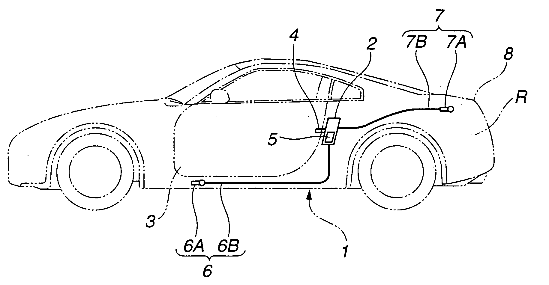
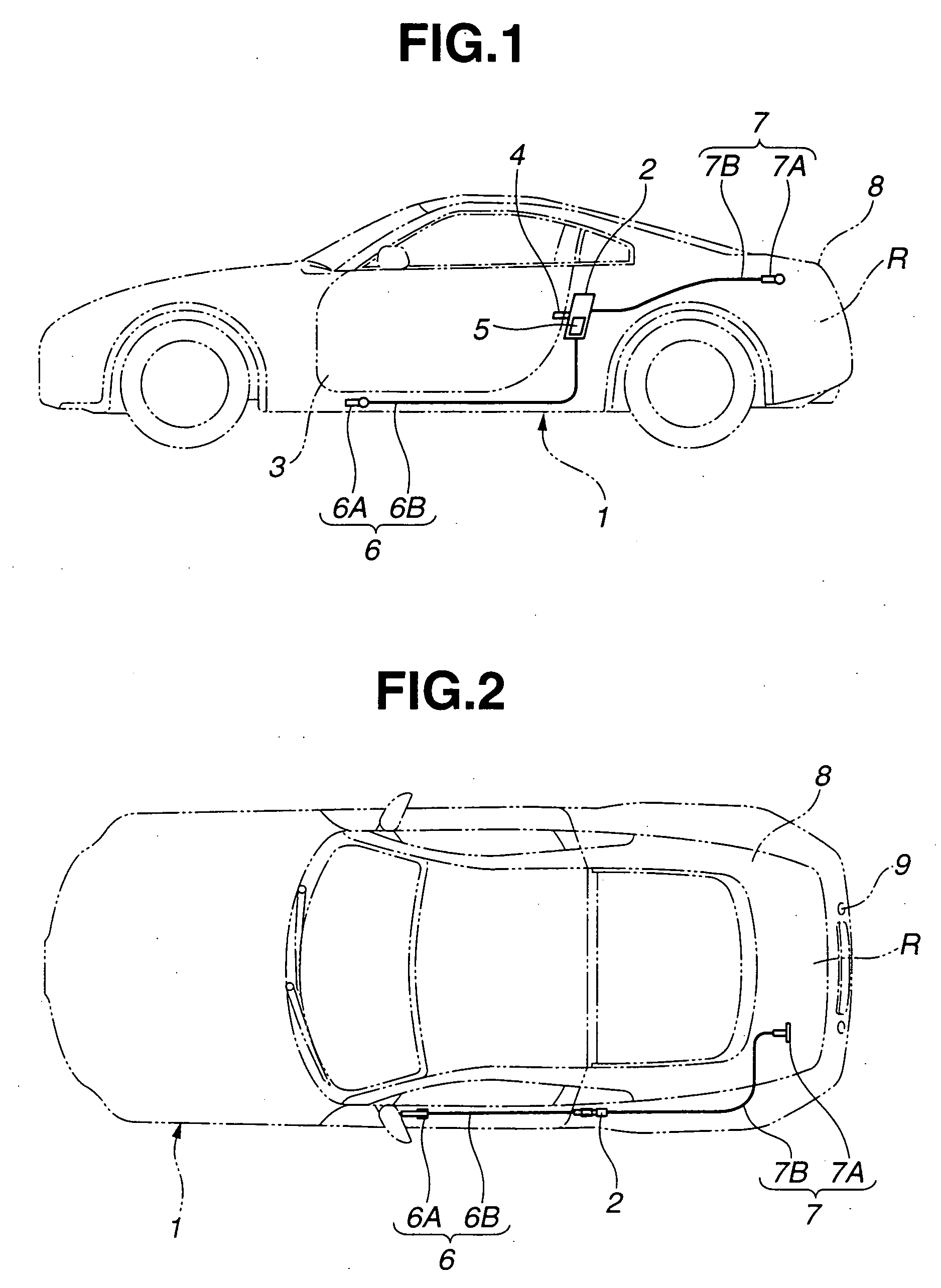
[0022] Referring to FIGS. 1 and 2, there is shown a motor vehicle to which an automotive door latch system of the present invention is practically applied.

[0023] In these drawings, denoted by numeral 1 is a body of the motor vehicle.

[0024] A latch unit 2 is mounted on the vehicle body 1 at a position just behind a door opening. A door 3 is pivotally connected at its front edge to the vehicle body 1 to open and close the door opening. Although not shown in the drawings, a suitable hinge mechanism is employed for the pivotal connection of the door 3 to the body 1. ...


PUM


Abstract

A door latch system of a motor vehicle comprises a latch unit mounted to the vehicle body. The latch unit has a latch condition to latch the door at a closed position and an unlatch condition to unlatch the door thereby to release the door. The system further comprises a power latch canceling mechanism mounted to the vehicle body. The power latch canceling mechanism includes an actuator that, when energized, enforcedly causes the latch unit to assume the unlatch condition. The system further comprises a manual latch canceling mechanism mounted to the vehicle body. The manual latch canceling mechanism includes a handle member that is placed at a position other than a vehicle cabin of the vehicle and a power transmitting member that transmits a movement of the handle member to the latch unit. The manual latch canceling mechanism causes the latch unit to assume the unlatch condition when the handle member is manipulated.

Description

BACKGROUND OF THE INVENTION [0001] 1. Field of the Invention [0002] The present invention relates in general to automotive door latch systems that are able to latch an automotive door to a vehicle body, and more particularly to the automotive door latch systems of a type having both a power latch canceling mechanism that cancels the latched condition of the door with the aid of a power produced by an actuator and a back-up manual latch canceling mechanism that cancels the latched condition of the door manually. [0003] 2. Description of the Related Art [0004] In order to clarify the task of the present invention, one known automotive door latch system of the above-mentioned type will be briefly described in the following, which is disclosed in Japanese Laid-open Utility Model Application (Jikkaisho) 63-146066. [0005] The door latch system of this publication generally comprises a striker fixed to a vehicle body and a latch unit mounted to a vehicle door. That is, when the door is bro...

Claims


Application Information

Patent Timeline
13 Apr 2006
Publication
US20060076788A1
IPC
E05B3/00; B60J5/00; E05B65/10; E05B79/20; E05B79/22; E05B81/04; E05B81/90; E05B83/36
CPC
E05B81/14; E05B81/90; E05B79/20; Y10S292/23; Y10S292/42; Y10T292/1047; Y10T292/1082; Y10T292/57
Inventors
GOTOU, SHINGO; OKAWA, SHINTARO