
Magnetic brake for braking a line spool of a fishing reel

a technology of magnetic brake and fishing reel, which is applied in the direction of fishing reels, applications, etc., can solve the problem that the braking effect cannot be fully cancelled, and achieve the effect of reducing the axial extent of the fishing reel and easily cancelling the braking effect of the magnetic brak

Inactive Publication Date: 2005-12-13
PURE FISHING
View PDF2 Cites 5 Cited by
  • Summary
  • Abstract
  • Description
  • Claims
  • Application Information

AI Technical Summary

Benefits of technology

[0004]The object of the present invention is to provide a magnetic brake, which requires but little space and thus makes it possible to reduce the axial extent of the fishing reel and the construction of which makes it possible to easily completely cancel the braking effect of the magnetic brake on the line spool.

Problems solved by technology

A further drawback is that the magnetic brake exerts a certain braking effect on the line spool even when the magnet support is displaced to its position furthest away from the line spool, i.e. the braking effect cannot be fully canceled.

Method used


Image

  • Magnetic brake for braking a line spool of a fishing reel
  • Magnetic brake for braking a line spool of a fishing reel
  • Magnetic brake for braking a line spool of a fishing reel

Examples


Embodiment Construction

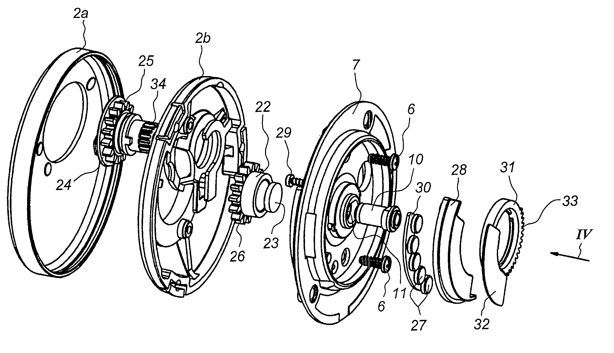
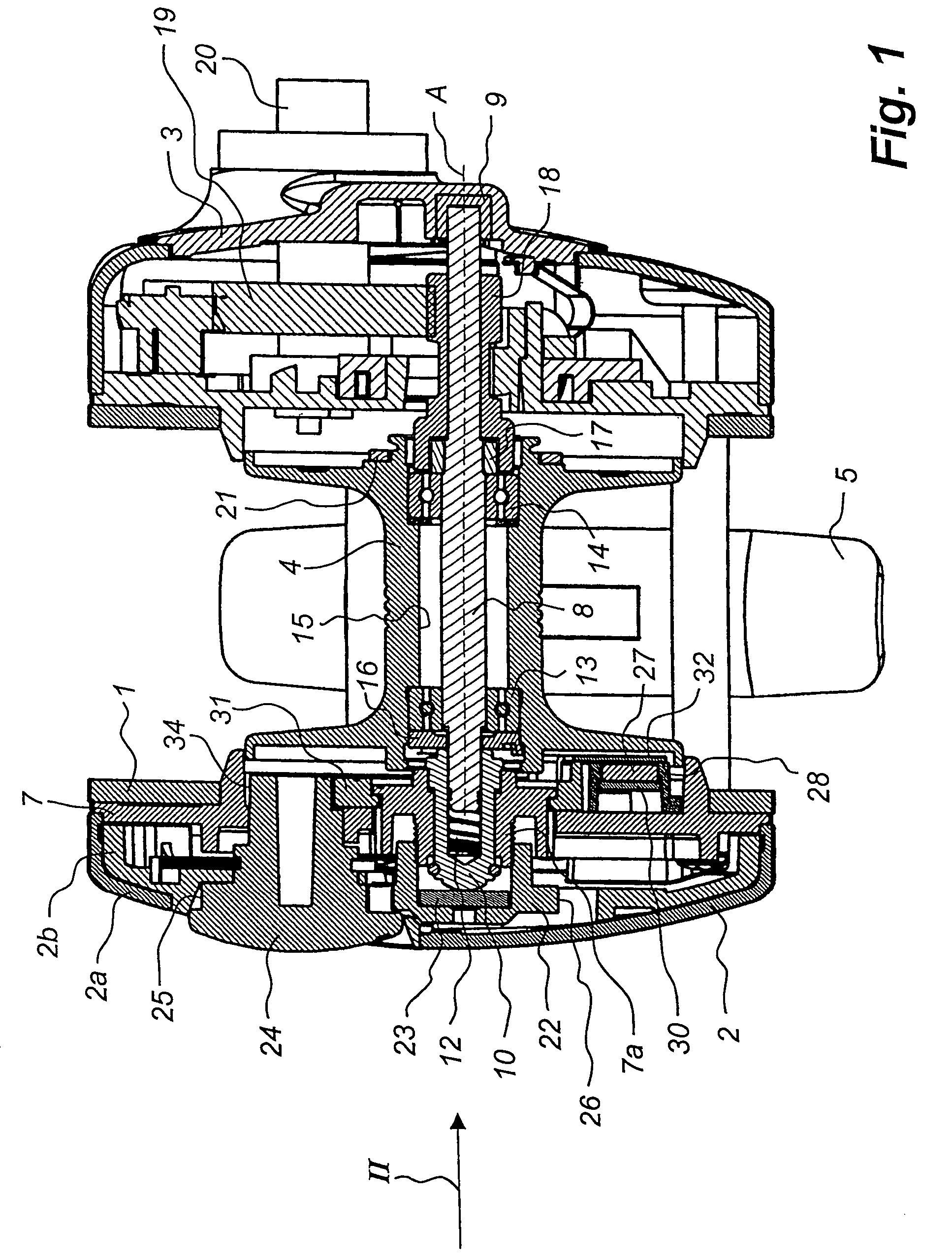
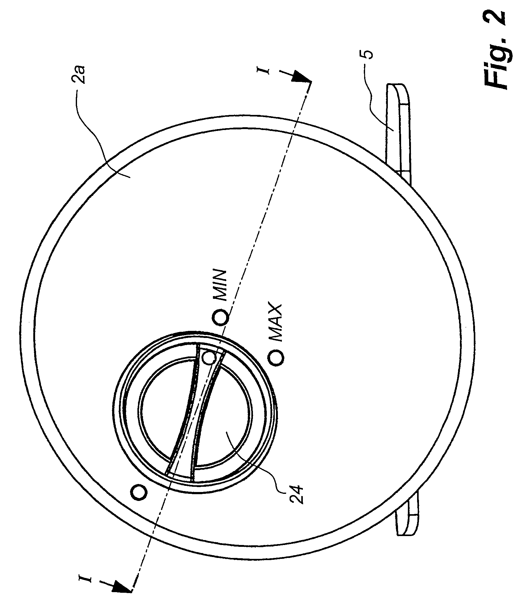
[0019]The multiplier type fishing reel shown in FIG. 1 has a frame 1, two side plates 2 and 3, a line spool 4 mounted in the frame 1 for receiving a line (not shown) and a foot 5 for mounting the fishing reel on a fishing rod (not shown).

[0020]The right side plate 3, which will not be described in detail here, is screwed to the frame 1. The left side plate 2 consists of a cap-shaped outer part 2a and a cap-shaped inner part 2b, to which the outer part 2a is snapped on. The inner part 2b is attached by means of screws 6 (FIG. 3) to a mounting plate 7 which in turn is screwed to the frame 1.

[0021]A line spool shaft 8 is at its one end inserted into a cup-shaped sleeve 9 which is fixed in the right side plate 3, and at its other end inserted into a cup-shaped sleeve 10 extending through the mounting plate 7. The sleeve 10 is non-rotatably but axially displaceably mounted in a through hole 11 (FIG. 3) in an externally threaded hub portion 7a projecting to the left and positioned on the ...


PUM


Abstract

An induction type magnetic brake for braking a line spool of a fishing reel having a frame, in which the line spool is supported rotatably about an axis of rotation, and two side plates which are mounted on the frame, the line spool having an end wall fixedly connected thereto and extending perpendicular to the axis of rotation, has a plurality of permanent magnets for inductive cooperation with the end wall of the line spool and a magnet support carrying the magnets and located between one of the side plates and the end wall of the line spool. The magnet support carries the magnets in a first plane perpendicular to the axis of rotation. A shielding plate is arranged in a second plane perpendicular to the axis of rotation and located between the first plane and the end wall of the line spool. The magnet support and the shielding plate are movable perpendicular to the axis of rotation and relative to each other to different relative positions, in which the shielding plate covers the magnets to different degrees.

Description

FIELD OF THE INVENTION[0001]The present invention relates to an induction type magnetic brake for braking a line spool of a fishing reel.[0002]A magnetic brake of this type is used for braking the line spool during casting, thereby to prevent rotation of the line spool at a speed higher than the payout speed of the line, which usually results in backlash with consequent tangling of the line.BACKGROUND ART[0003]A magnetic brake of this type is known from, for instance, U.S. Pat. No. 4,580,742. This known magnetic brake has a plurality of permanent magnets for inductive cooperation with the line spool and a magnet support carrying the magnets. In this known magnetic brake, the braking effect of the brake on the line spool is controlled like in most prior-art magnetic brakes of this kind by the magnet support being displaced in the axial direction of the line spool shaft. This displacement is brought about by turning an adjusting knob. When the braking effect of the brake on the line s...

Claims


Application Information

Patent Timeline
Patent Type & Authority Patents(United States)
IPC IPC(8): A01K89/0155
CPCA01K89/01555
Inventor MOOSBERG, BORJE
Owner PURE FISHING
Learn More