
Electro-hydraulic Motor Vehicle Brake System And Method For The Operation Thereof

a technology of electrohydraulic motor vehicles and brake systems, which is applied in the direction of braking systems, vehicle components, foot actuation initiations, etc., can solve the problems that the axial extent of hydraulic pressure generators is long and can furthermore have a negative influence on the crash safety of vehicles, so as to reduce the axial extent of hydraulic pressure generator components.

Active Publication Date: 2016-10-20
LUCAS AUTOMOTIVE GMBH
View PDF13 Cites 7 Cited by
  • Summary
  • Abstract
  • Description
  • Claims
  • Application Information

AI Technical Summary

Benefits of technology

The patent describes a configuration where two cylinder-piston devices can be placed very close to each other and managed separately. This reduces the size of the hydraulic pressure generator components. The technical effect of this is that the device is more compact and easier to manage.

Problems solved by technology

Hydraulic pressure generators with a long axial extent can furthermore have a negative influence on the crash safety of a vehicle.

Method used


Image

  • Electro-hydraulic Motor Vehicle Brake System And Method For The Operation Thereof
  • Electro-hydraulic Motor Vehicle Brake System And Method For The Operation Thereof
  • Electro-hydraulic Motor Vehicle Brake System And Method For The Operation Thereof

Examples


Embodiment Construction

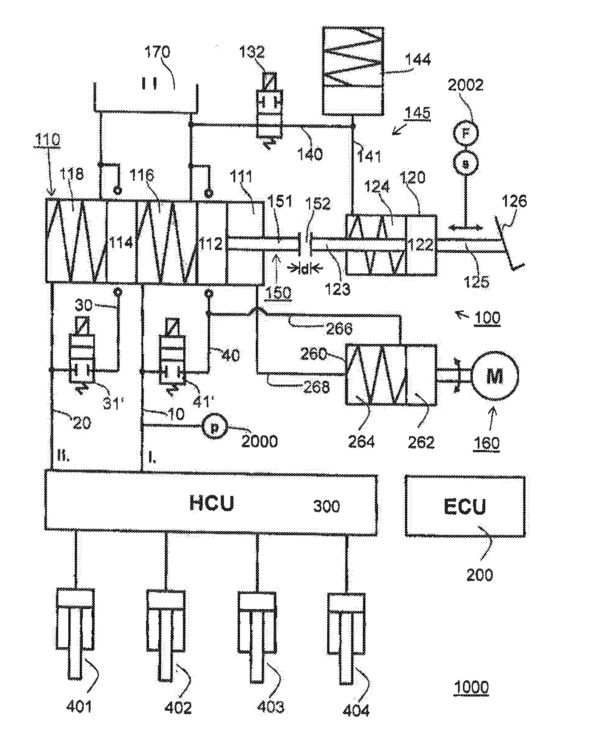
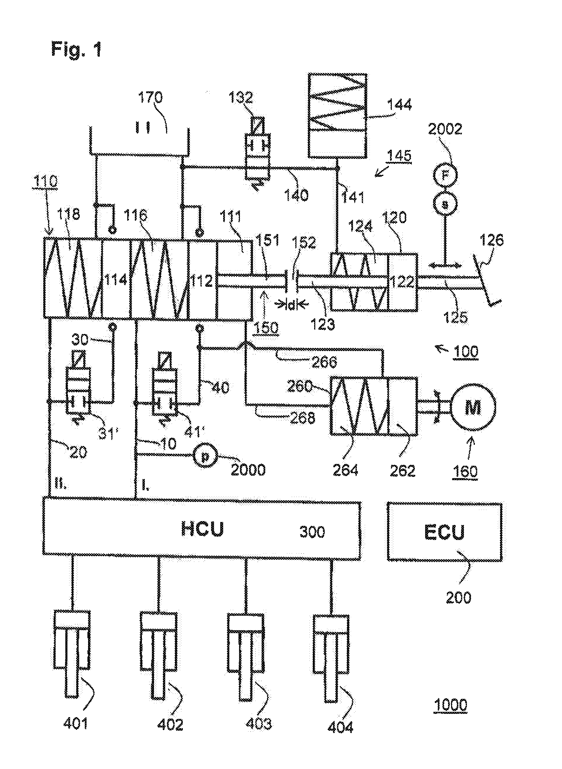
[0032]Referring now to the drawings, FIG. 1 shows an embodiment of an electro-hydraulic motor vehicle brake system 1000. The variant shown in FIG. 1 is a dual circuit brake system with a first brake circuit 10 and a second brake circuit 20. The present invention is not dependent on the number of brake circuits in the brake system 1000.

[0033]The brake system 1000 comprises a hydraulic pressure generator assembly 100 which is fluidically coupled to the to brake circuits 10, 20, a simulator circuit 145 which is fluidically coupled to the assembly 100, a centrally arranged hydraulic fluid reservoir 170, and a fluid path 140 which fluidically couples the hydraulic fluid reservoir 170 and the simulator circuit 145 and has a valve 132 arranged therein. The brake system 1000 further comprises sensor technology 2000, 2002 for the quantitative detection of an intention on the part of the driver (e.g. detection of a pedal travel s and / or an actuating force F on the brake pedal 126) as well as ...


PUM


Abstract

An electro-hydraulic motor vehicle brake system is provided, having a first cylinder-piston device, which can be fluidically coupled to at least one wheel brake of the brake system, for generating hydraulic pressure on the at least one wheel brake, wherein the first cylinder-piston device comprises at least one first piston. The brake system further has a second cylinder-piston device, which comprises at least one second piston, and an electromechanical actuator which acts on the second piston of the second cylinder-piston device. The second cylinder-piston device is or can be fluidically coupled at the output side to the first piston of the first cylinder-piston device in order to provide a hydraulic pressure, which is generated in the second cylinder-piston device upon actuation of the electromechanical actuator, for actuating the at least one first piston of the first cylinder-piston device.

Description

CROSS-REFERENCE TO RELATED APPLICATIONS[0001]This application is the National Phase of International Application PCT / EP2014 / 073174 filed Oct. 29, 2014 which designated the U.S. and was published on Jun. 4, 2015 as International Publication Number WO 2015 / 078651 A1. PCT / EP2014 / 073174 claims priority to German Patent Application No. 10 2013 018 073.2, filed Nov. 28, 2013. Thus, the subject nonprovisional application claims priority to German Patent Application No. 10 2013 018 073.2, filed Nov. 28, 2013. The disclosures of these applications are incorporated herein by reference.BACKGROUND OF THE INVENTION[0002]The present disclosure relates to the field of brake systems in general. An electro-hydraulic motor vehicle brake system is described in concrete terms. Modern motor vehicle brake systems operate according to the “brake-by-wire” principle. This means that a hydraulic pressure is built up on the wheel brakes by way of a hydraulic pressure generator, independently of a foot force. ...

Claims


Application Information

Patent Timeline
Patent Type & Authority Applications(United States)
IPC IPC(8): B60T13/66B60T7/06B60T13/74
CPCB60T13/66B60T7/06B60T13/741B60T8/4077B60T8/4086
Inventor KNECHTGES, CARSTENKNECHTGES, JOSEF
Owner LUCAS AUTOMOTIVE GMBH
Learn More