Device for locking an electrical device to an accessory part

a technology for locking electrical devices and accessories, which is applied in the direction of couplings, portable power-driven tools, cell components, etc., can solve the problems of property damage or injury, and the two-stage locking mechanism is unable to reliably prevent the battery pack from falling out, so as to achieve the effect of easy exertion of force on the accessory par

Active Publication Date: 2006-04-27
ROBERT BOSCH GMBH
View PDF9 Cites 19 Cited by
  • Summary
  • Abstract
  • Description
  • Claims
  • Application Information

AI Technical Summary

Benefits of technology

[0011] Since battery packs are usually removed while power tools are being held in their normal operating position in which the battery pack is pointing downward, the force acting on the accessory part can easily be exerted by the weight of the battery pack if its center of gravity is lower in the safety position than during its movement along the guide and gravity consequently pulls the battery pack downward into the safety position. But since this orientation is not necessarily always maintained and could also be different in other electrical devices, in a preferred embodiment of the present invention, the force acting on the accessory part is a spring force that pushes or pulls the accessory part into the safety position and has the advantage over gravity that it works regardless...

Problems solved by technology

This can result in the battery pack slipping out of the guide during transport or operation of the power tool when the latter is tilted downward toward the removal position, which can lead to property damage or injury.
But if the user does not h...

Method used


Image

  • Device for locking an electrical device to an accessory part
  • Device for locking an electrical device to an accessory part
  • Device for locking an electrical device to an accessory part

Examples


Embodiment Construction

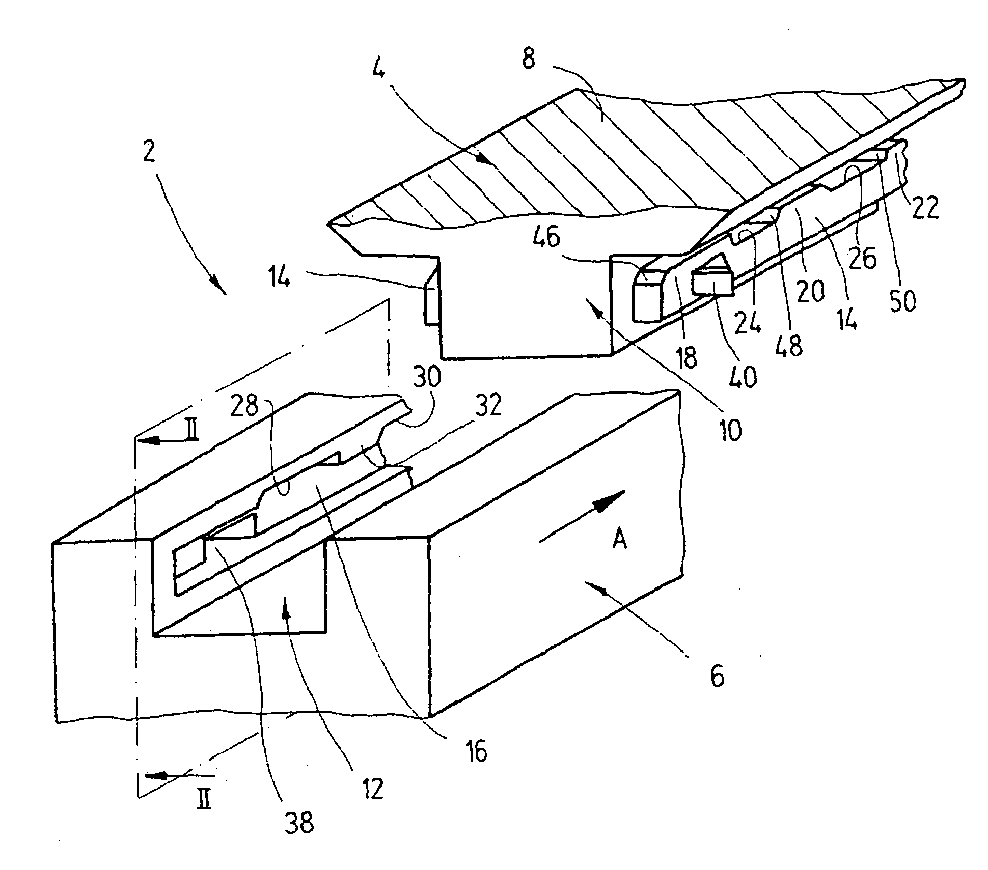
[0026] The locking devices 2 shown in the drawings are used to lock a cordless power tool 4, for example a hand-guided percussion drill, to a battery pack 6 required to supply power to the power tool 4.

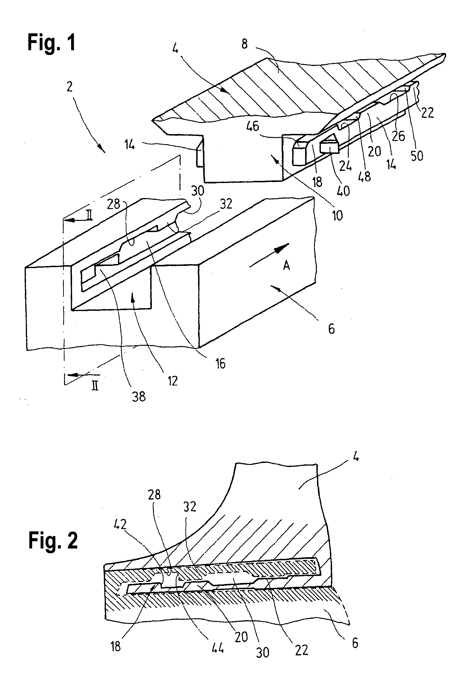
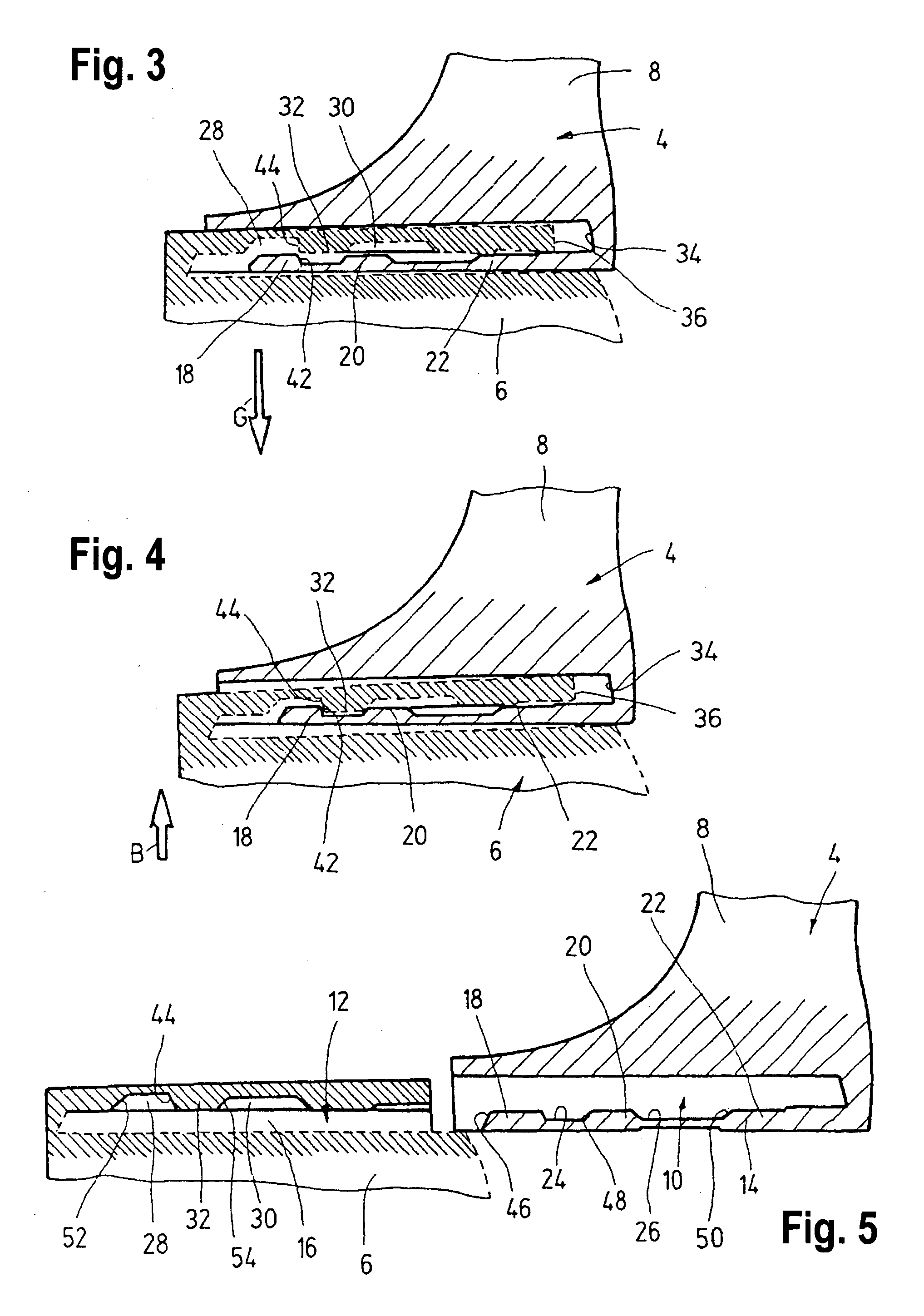
[0027] As best shown in FIGS. 1 through 5, on the free lower end of its handle 8, the power tool 4 is provided in a known fashion with a protruding guide rail 10 that can be slid in the direction of the arrow A into a guide groove 12 let into the upper end of the battery pack 6. This guide groove 12 has a cross section complementary to the cross section of the guide rail 10 and, together with it, constitutes a linear guide that defines the predetermined insertion direction (arrow A).

[0028] The guide rail 10 is provided with two laterally protruding guide strips 14, whose cross sections essentially correspond to the cross sections of two guide slots 16 (only one of which is visible in FIG. 1) situated opposite from each other inside the guide groove 12. The tops of the two guide stri...


PUM


Abstract

A device for locking, an electrical device to an accessory part has a guide configured to guide the accessory part in a predetermined movement direction as it moves between a locking position in which it is locked the electrical device and a removal position in which it is removed from the electrical device, the guide having a break in at least one location between the locking position and removal position, and at the location a force acting on the accessory part moves the accessory part into a safety position in which the accessory part is prevented from moving further along the guide into the removal position.

Description

BACKGROUND OF THE INVENTION [0001] The present invention relates to a device for locking an electrical device to an accessory part. [0002] Locking devices of this type are used, for example, to reliably connect cordless hand-guided power tools to a battery pack used as a power supply. [0003] The known locking devices usually have a linear guide provided on the power tool into which the battery pack is slid until, after being slid all the way in, it comes into contact with a stop and is locked in this position in relation to the power tool, while simultaneously producing an electrical connection between a battery of the battery pack and an electrical circuit of a consumer of the power tool. The locking usually occurs with the aid of a latch, which is supported in a housing of the power tool so that it can move in opposition to the force of a spring and which the spring force brings into engagement with a detent recess in the battery pack. A release mechanism is used to release the co...

Claims


Application Information

Patent Timeline
IPC IPC(8): E21B17/046B25F5/02H01M50/204H01M50/244H01M50/247H01M50/262
CPCB25F5/02H01M2/1022Y10T403/59Y10T403/32442Y10T403/591Y10T403/32451Y10T403/604Y10T403/599Y10T403/61Y10T403/60Y02E60/10H01M50/204
Inventor REJMAN, MARCINMATTHIAS, WOLF
Owner ROBERT BOSCH GMBH
Why Eureka
Try Eureka