Engine driven power supply device

Inactive Publication Date: 2006-07-27
KOKUSAN DENKI CO LTD
View PDF14 Cites 6 Cited by
  • Summary
  • Abstract
  • Description
  • Claims
  • Application Information

AI Technical Summary

Benefits of technology

[0007] An object of the present invention is to provide an engine driven power supply device that can eliminate the risk of electrical leakage or electrical shocks and continued wasting of energy when a connector provided between an output end of a power supply device body and a receptacle is separated by vibrations or the like.
[0010] Comprised as described above, the electrical equipment required for maintaining the operation of the engine stops the operation thereof to stop the engine, thereby stopping an output of the generator when the connector is separated. This prevents electrical leakage or electrical shocks when the connector is separated and a terminal thereof is exposed, thereby improving safety. Further, the engine is stopped with the connector being separated, thereby preventing energy from being wasted in a state where the load cannot be driven.
[0019] Also, in the case where a connector state detection switch that holds an ON state when the connector is separated and holds an OFF state when the connector is connected is provided in the connector, an ignition device may be comprised so as to perform an ignition operation only when an ignition allowing signal is generated, thereby allowing the ignition operation only when the connector is connected, and preventing the ignition operation when the connector is separated.
[0022] As described above, also in the case where the ignition allowing signal generation circuit that generates the ignition allowing signal when the connector is connected and stops the generation of the ignition allowing signal when the connector is separated is provided so that the ignition device functions only when the ignition allowing signal is generated, the engine can be stopped when the connector is separated. This prevents electrical leakage or electrical shocks when the connector is separated and the terminal thereof is exposed, and prevents energy from being wasted.
[0023] As described above, according to the present invention, the operation of the electrical equipment required for maintaining the operation of the engine when the connector is separated is stopped to stop the engine, thereby stopping the output of the generator. This prevents electrical leakage or electrical shocks when the connector is separated by vibrations or the like of the engine, thereby improving safety, and prevents energy from being wasted.

Problems solved by technology

In the engine driven power supply device comprised as described above, if the connector provided between the output end of the power supply device body and the receptacle is separated by vibrations of the engine or an external impact or the like during an operation, conductive components around a terminal to which a voltage of the connector is applied may come into contact with the terminal to cause electrical leakage or electrical shocks.

Method used


Image

  • Engine driven power supply device
  • Engine driven power supply device
  • Engine driven power supply device

Examples


first embodiment

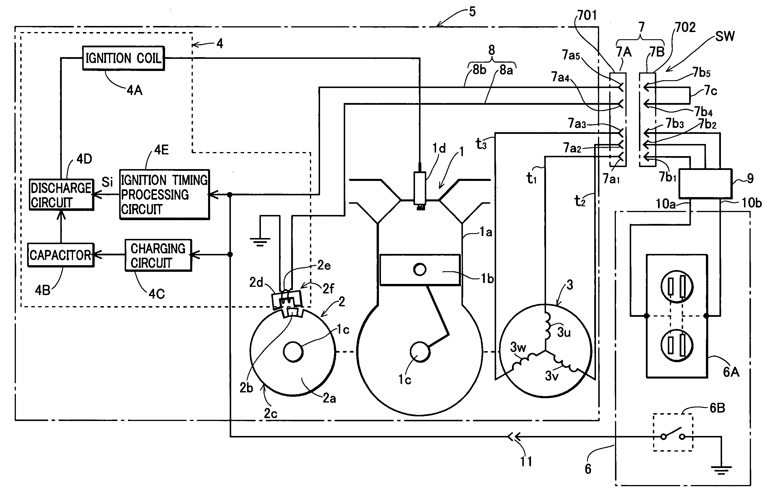
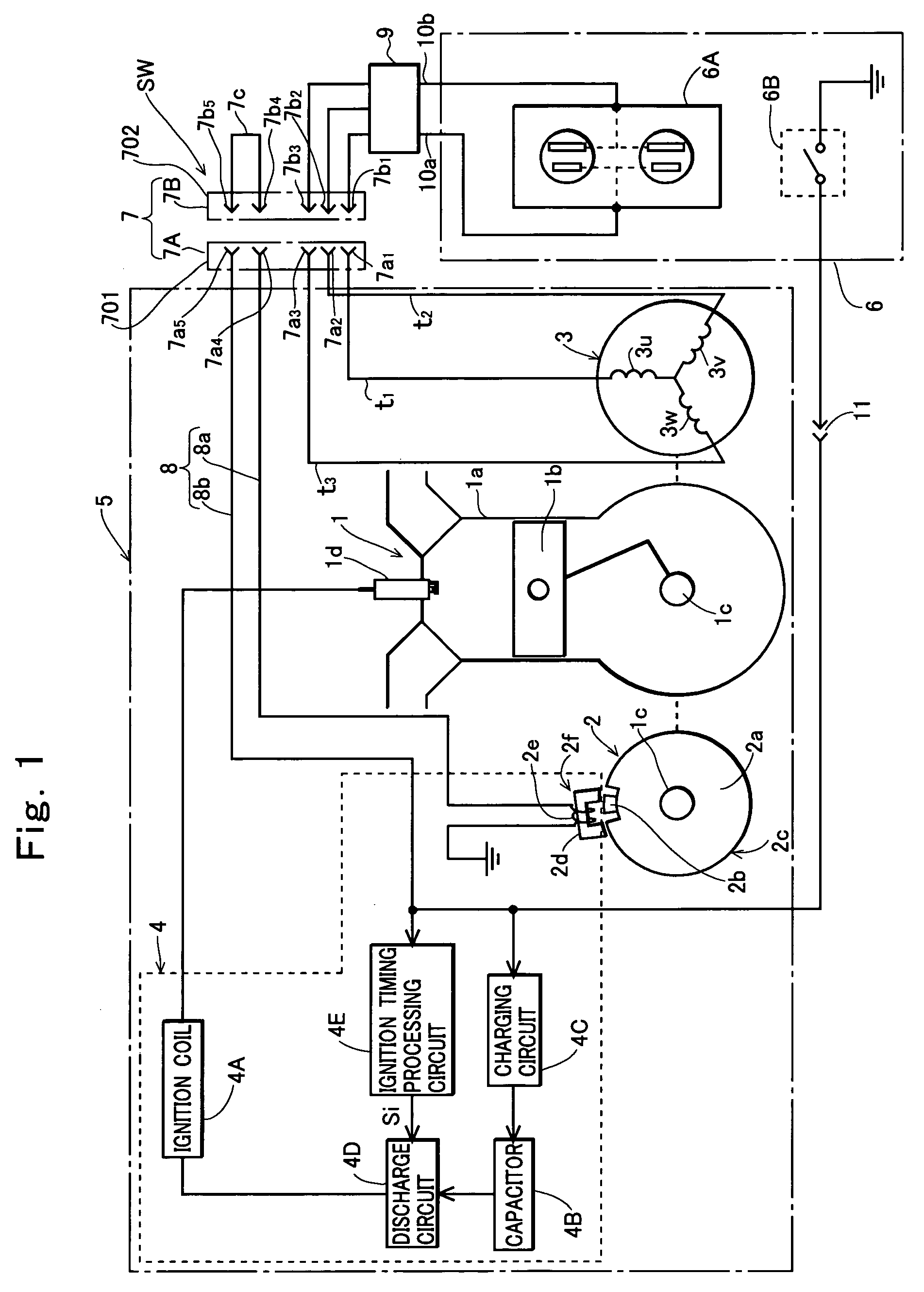
[0034] Now, preferred embodiments of the present invention will be described in detail with reference to the drawings. FIG. 1 shows a construction of the present invention, and in FIG. 1, a reference numeral 1 denotes an engine including a cylinder 1a, a piston 1b, a crankshaft 1c, an ignition plug 1d, or the like, reference numerals 2 and 3 denote a first generator and a second generator driven by the engine 1, and a reference numeral 4 denotes an ignition device that ignites the engine 1.

[0035] The first generator 2 used in the embodiment is a magnetic AC generator including a magnet rotor 2c comprised by mounting a permanent magnet 2b to an outer periphery of a flywheel 2a mounted to the crankshaft 1c of the engine, and a stator 2f comprised by winding an exciter coil 2e around a core 2d having, at opposite ends thereof, magnetic pole portions that face magnetic poles of the magnet rotor 2c formed on the outer periphery of the flywheel. This generator induces an AC voltage in the...

third embodiment

[0058]FIG. 4 shows the present invention, and also in this embodiment, contacts 7b4 and 7b5 of a connector 7 are connected by a jumper wire 7c, and a connector state detection switch that holds an OFF state when the connector 7 is separated and holds an ON state when the connector 7 is connected is provided in the connector 7.

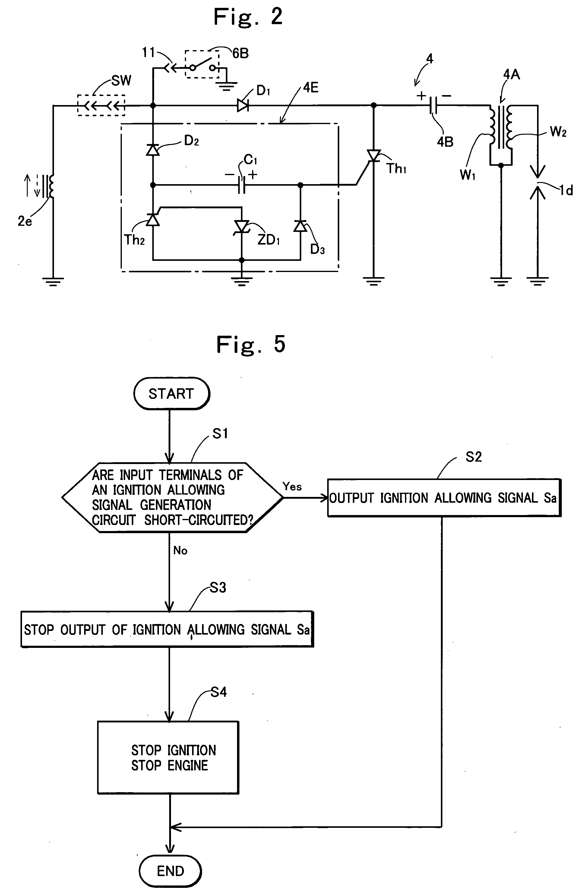
[0059] In this embodiment, an ignition allowing signal generation circuit 4F that has input terminals 4f1 and 4f2 and generates an ignition allowing signal Sa when the input terminals are short-circuited is provided in an ignition device 4, and the input terminals 4f1 and 4f2 are connected to fourth and fifth contacts 7a4 and 7a5 of a first connector half 7A via wires 8a and 8b, respectively, to connect the connector state detection switch SW between the input terminals 4f1 and 4f2. The ignition allowing signal Sa generated by the ignition allowing signal generation circuit 4F is input to the ignition timing processing circuit 4E. The ignition timing processing...

fourth embodiment

[0064]FIG. 6 shows the present invention. In this embodiment, a connector 7 is comprised of a first connector half 7A including first to fourth female contacts 7a1 to 7a4 in a connector shell 701 and a second connector half 7B including first to fourth male contacts 7b1 to 7b4 connected to the contacts 7a1 to 7a4 in a connector shell 702. Also, three-phase output terminals t1 to t3 of a power supply device body are connected to the contacts 7a1 to 7a3, respectively, of the first connector half 7A, and the contacts 7b1 to 7b3 are connected to input terminals of a power conversion unit 9.

[0065] Also in this embodiment, a connector state detection switch SW that holds an OFF state when the connector 7 is separated and holds an ON state when the connector 7 is connected is comprised of the contacts 7a4 and 7b4 of the connector 7. An ignition allowing signal generation circuit 4F includes one input terminal 4f and is comprised so as to generate an ignition allowing signal Sa only when th...


PUM


Abstract

An engine driven power supply device in which a load connecting receptacle is connected, via a connector, to an output end of a power supply device body that outputs power required for driving a load using a generator driven by an engine as a power supply, wherein a connector state detection switch that holds an OFF state when the connector is separated and holds an ON state when the connector is connected is provided in the connector, the connector state detection switch is inserted between an ignition for the engine and an exciter coil that provides a power supply voltage to the ignition device so that an operation of the ignition device is stopped when the connector is separated.

Description

TECHNICAL FIELD OF THE INVENTION [0001] The present invention relates to an engine driven power supply device that supplies power to a load using a generator driven by an engine as a power supply. BACKGROUND OF THE INVENTION [0002] Engine driven power supply devices include an engine generator that supplies commercial AC power to a load using a generator driven by an engine as a power supply as disclosed in Japanese Patent Application Laid-Open Publication No. 2001-15937 or an engine welder that supplies power to a welding load using a generator driven by an engine as a power supply as disclosed in Japanese Patent Application Laid-Open Publication No. 2004-276115. [0003] Such a power supply device includes a power supply device body that outputs power required for driving a load and a load connecting receptacle connected to an output end of the power supply device body via a connector, and supplies power from the power supply device body to the load via the connector, the receptacle...

Claims


Application Information

Patent Timeline
IPC IPC(8): H02P9/00
CPCF02D29/06
Inventor SEKITA, TOMOAKIKISHIBATA, KAZUYOSHIKITAGAWA, YUICHISATO, HIROYASU
Owner KOKUSAN DENKI CO LTD
Why Eureka
Try Eureka