Switching method and apparatus

a technology of switching method and apparatus, applied in the field of method and network element, can solve the problems of increasing complexity and maintenance of call control application

Inactive Publication Date: 2006-08-31
NOKIA SOLUTIONS & NETWORKS OY
View PDF4 Cites 0 Cited by
  • Summary
  • Abstract
  • Description
  • Claims
  • Application Information

AI Technical Summary

Benefits of technology

[0012] It is therefore an object of the present invention to provide a method and apparatus for performing a switching operation in a telecommunication network, by means of which the problems associated with different switching technologies can be solved.
[0018] Accordingly, physical resources of the switch are abstracted to a logical model which provides a clear interface for call control and signaling applications. The logical model consists of sides and logical services. The logical resources are controlled by the logical resource managing means, such that details of the resources are hidden behind the abstract logical resource. Thereby, the problems associated with different switching technologies can be solved, since switching technology independent resources are provided for call control applications, and the same control software can be used for different physical resources. The call control applications complexity and maintenance are therefore reduced, since they can handle logical resources and there is no need for different versions of the applications in different switching techniques.
[0022] Alternatively, the converting step may be implemented as a process family having a hand process for each call, wherein one hand process takes care of resources of a corresponding call. Due to the hand processes, the internal structure of the program block can be simplified. The resources of a call are collected at one place and the performance is increased by using the hand processes. Furthermore, an easy maintenance can be achieved due to the simplified implementation. The logical resource interface can thus be distributes over several computers, preferably the same computers as used for the signaling and call control processes of the switching apparatus. The interface may be implemented on any other hardware platform, such as ATM (Asynchronous Transfer Mode), TDM (Time Divisional Multiplex) hardware, or IP (Internet Protocol) based frame relay hardware.

Problems solved by technology

Thus, in switching network elements, a problem arises that complexity and maintenance of call control applications increases due to the combined use of different versions of the applications in different switching techniques or different network generations.

Method used


Image

  • Switching method and apparatus
  • Switching method and apparatus
  • Switching method and apparatus

Examples


Embodiment Construction

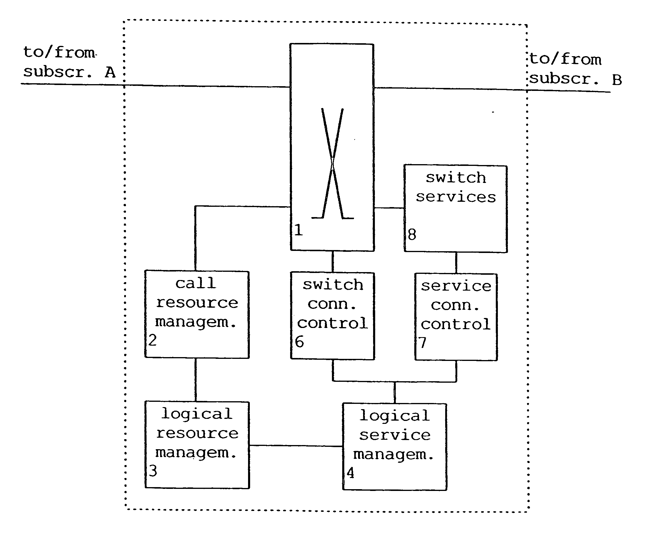
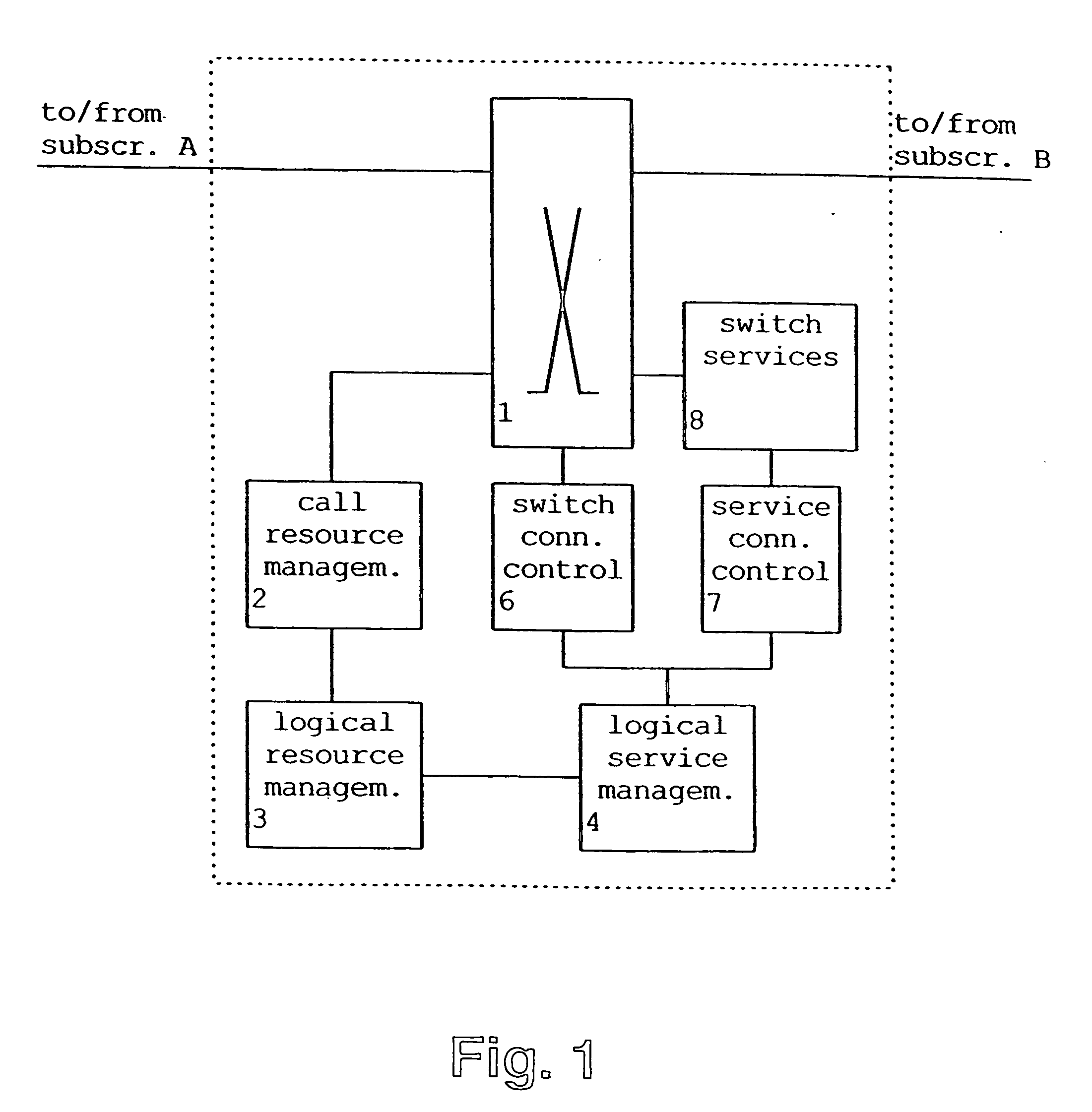
[0038] In the following, the preferred embodiment of the switching method and apparatus according to the present invention will be described on the basis of a switching network element as shown in FIG. 1.

[0039] According to FIG. 1, the switching network element according to the preferred embodiment comprises a switching unit 1 such as an ATM switch or a TDMA switch, which is arranged for switching connections between a subscriber A and a subscriber B. Moreover, the switching unit 1 may switch the connection of the subscriber A or the connection of the subscriber B to a switch service unit 8 to thereby provide the respective connection with switching service functions such as tone or announcement generators, push button receivers, multi party conference call functions and the like. The switch service unit 8 is controlled by a service connection control unit 7 which is arranged to control the switch service unit 8 so as to provide a requested service function at a service point to wh...


PUM


Abstract

The present invention relates to a switching method and apparatus for performing a switching operation in a telecommunication network, wherein a side information and a service information generated based on a received call is converted into a switching technology independent identification information for identifying a start point and an end point of a connection to be switched in the switching apparatus. Thus, the physical resources of the switch are abstracted to a logical model which provides a clear interface for call control and signaling applications. Logical resources are controlled by resource managers, such that the physical resources are hidden by the switching technology independent identification information of the start point and end point of the connection. Thereby, problems with different switching technologies can be solved, and the complexity and maintenance of call control applications can be reduced, since they handle logical resources independent of the switching techniques.

Description

CROSS-REFERENCE TO RELATED APPLICATION [0001] This application is a continuation of U.S. patent application Ser. No. 10 / 076,913, filed on Feb. 13, 2002, which in turn is a continuation application of International Application PCT / EP99 / 06503 having an international filing date of Sep. 3, 1999 and from which priority is claimed under all applicable sections of Title 35 of the United States Code including, but not limited to, Sections 120, 363 and 365(c).FIELD OF THE INVENTION [0002] The present invention relates to a method and network element for performing switching between an incoming side and outgoing side of the network element in a telecommunication network such as a third generation mobile network. BACKGROUND OF THE INVENTION [0003] In the near future, multimedia applications will in full scale enter the world of cellular communications. To support new services, which will set new demands on the infrastructure for radio communications, a new wireless communication system needs ...

Claims


Application Information

Patent Timeline
Patent Type & Authority Applications(United States)
IPC IPC(8): H04L12/50H04L12/56H04L49/111H04Q11/04
CPCH04L49/253H04L49/254H04L49/255H04L49/3081H04L49/355H04L2012/5626H04L2012/563H04Q11/0478
Inventor TILANDER, SAMI
Owner NOKIA SOLUTIONS & NETWORKS OY
Why Eureka
Try Eureka