Image forming apparatus

a technology of forming apparatus and forming cassette, which is applied in the direction of thin material processing, instruments, article separation, etc., can solve the problems of large apparatus size, large paper feeding cassette total weight, and inability to store large-sized paper sheets as many as small-sized paper sheets, and achieve high operability and effectively accommodate other members

a technology of forming apparatus and forming cassette, which is applied in the direction of thin material processing, instruments, article separation, etc., can solve the problems of large apparatus size, large paper feeding cassette total weight, and inability to store large-sized paper sheets as many as small-sized paper sheets, and achieve high operability and effectively accommodate other members

US20060222434A1Inactive Publication Date: 2006-10-05KYOCERA DOCUMENT SOLUTIONS INC

Image

  • Image forming apparatus
  • Image forming apparatus
  • Image forming apparatus

Examples


Embodiment Construction

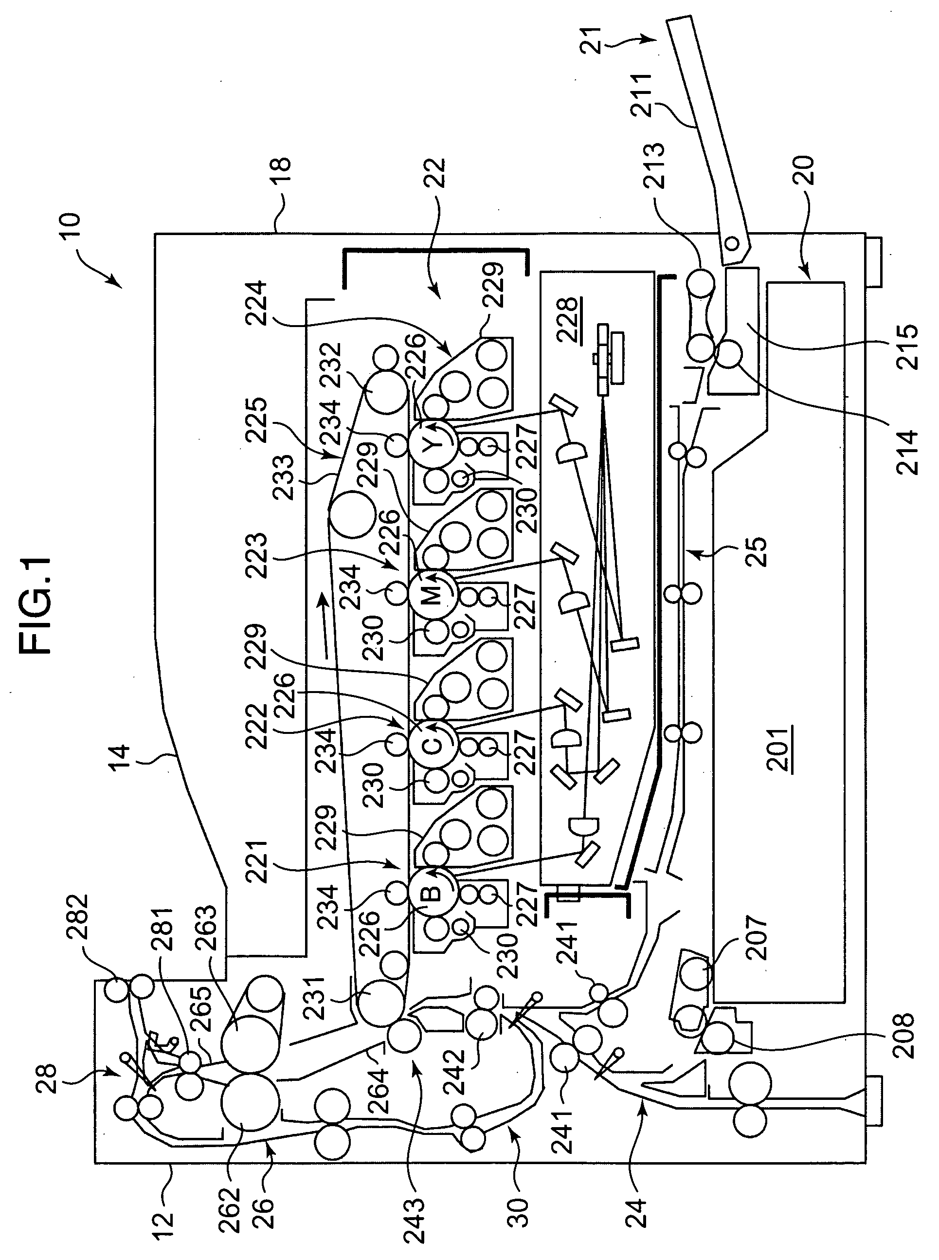
[0020]FIG. 1 is a diagram showing a schematic construction of an image forming apparatus according to an embodiment of the invention. An image forming apparatus 10 shown in FIG. 1 is a tandem color printer, and is constructed by a main body portion 12 and a paper sheet discharging portion 14. The main body portion 12 is adapted to form a color image on a paper sheet. The paper sheet discharging portion 14 is adapted to discharge the paper sheet on which a color image has been formed in the main body portion 12.

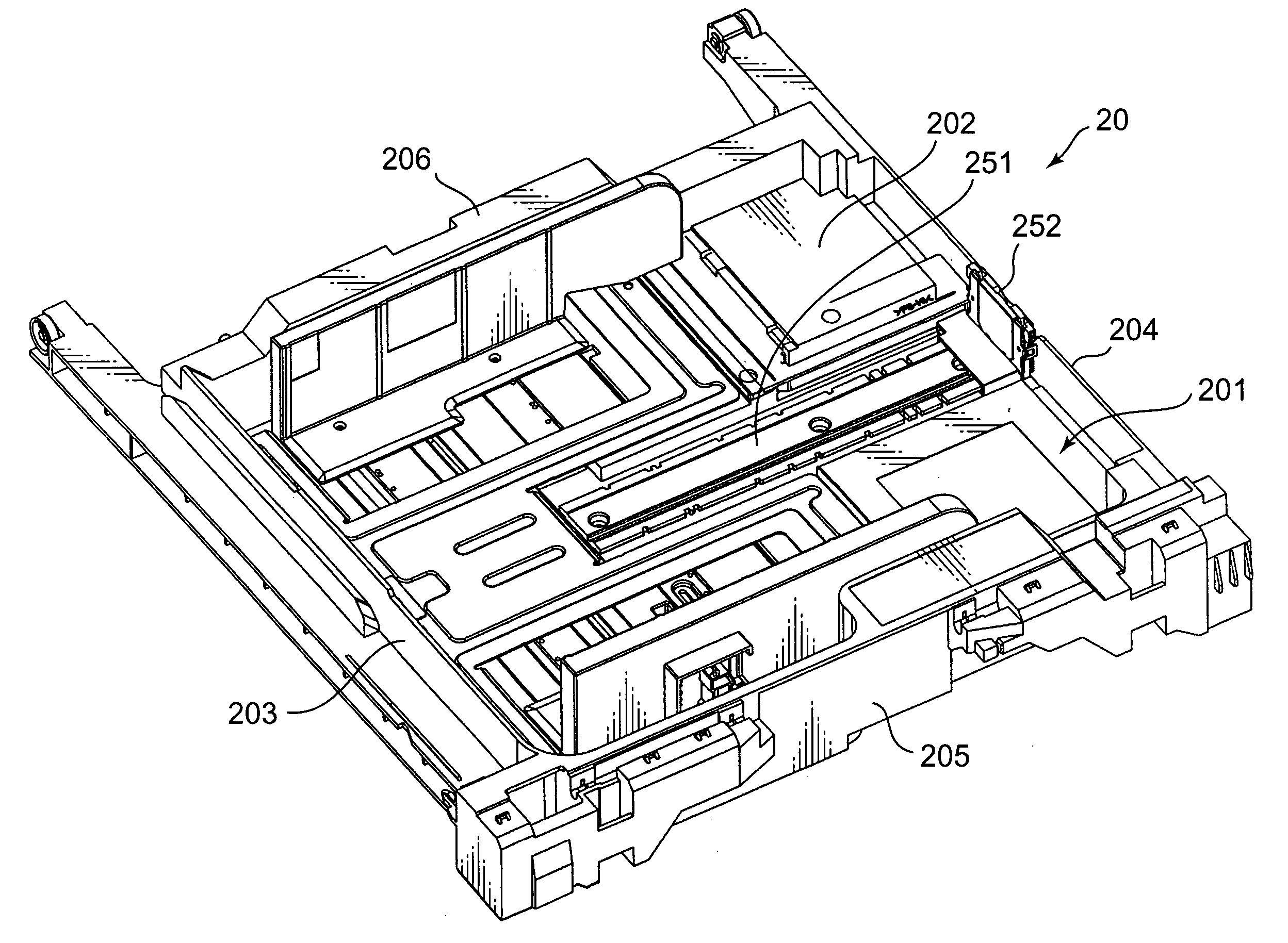
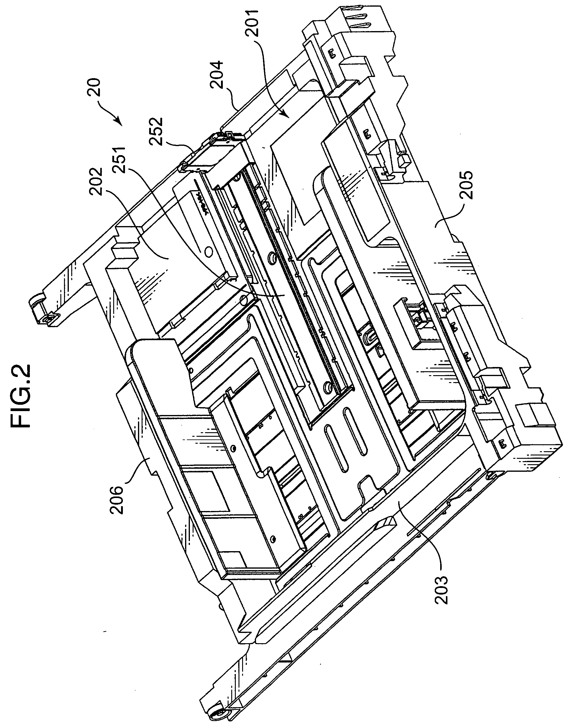
[0021] The main body portion 12 includes a paper feeding cassette 20, a stack tray 21, an image forming section 22, a first conveyance passage 24, a second conveyance passage 25, a fixing unit 26, and a third conveyance passage 28. The paper feeding cassette 20 is mounted in a lower part of a housing 18 and is adapted to store paper sheets. The stack tray 21 is mounted in an intermediate part of the housing 18 and is adapted to feed paper sheets for manual feeding. The image ...


PUM


Abstract

An image forming apparatus comprising: a paper feeding cassette which selectively stores at least two kinds of paper sheets having different size with respect to a paper feeding direction, and includes a posterior end cursor which restricts a posterior end position of the stored paper sheets with respect to the paper feeding direction, wherein the height of the posterior end cursor is changeable. According to this construction, a smaller space is provided to stack large-sized paper sheets which are not frequently used while a larger space is provided to stack small-sized paper sheets which are frequently used can be reserved.

Description

BACKGROUND OF THE INVENTION [0001] 1. Field of the Invention [0002] The present invention relates to an image forming apparatus such as a printer, a copying machine, a facsimile apparatus, a composite machine which has functions of copying, facsimile, and the like. [0003] 2. Description of the Related Art [0004] Generally, an image forming apparatus includes a paper feeding cassette which selectively stores at least two kinds of paper sheets having different size with respect to a paper feeding direction. However, in a conventional image forming apparatus disclosed in Japanese Unexamined Patent Publication Nos. HEI 05-330674 and HEI 06-135571, for example, a cursor which restricts a posterior end of paper sheets stacked in the paper feeding cassette with respect to the paper feeding direction is held at a fixed height. [0005] Image forming apparatuses of the prior art listed above need a paper feeding cassette which stores a large number of small-sized paper sheets since small-sized...

Claims


Application Information

Patent Timeline
05 Oct 2006
Publication
US20060222434A1
IPC
B65H1/04
CPC
B65H1/04; B65H2701/1131; B65H2405/1122
Inventors
KITAMURA, TAKATOYO; HATAKEYAMA, CHISATO