Antenna device having rotatable structure

Inactive Publication Date: 2006-12-07
JOYMAX ELECTRONICS CO LTD
View PDF8 Cites 4 Cited by
  • Summary
  • Abstract
  • Description
  • Claims
  • Application Information

AI Technical Summary

Benefits of technology

[0008] The primary objective of the present invention is to provide an antenna device including a rotatable structure

Problems solved by technology

For example, U.S. Pat. No. 6,341,217 to Wong discloses one of the typical portable telephones including a shielded transmission antenna that is solidly secured to the typical portable telephone, and may not be extended relative to the typical portable telephone, such that the typical portable telephones m

Method used


Image

  • Antenna device having rotatable structure
  • Antenna device having rotatable structure
  • Antenna device having rotatable structure

Examples


Example

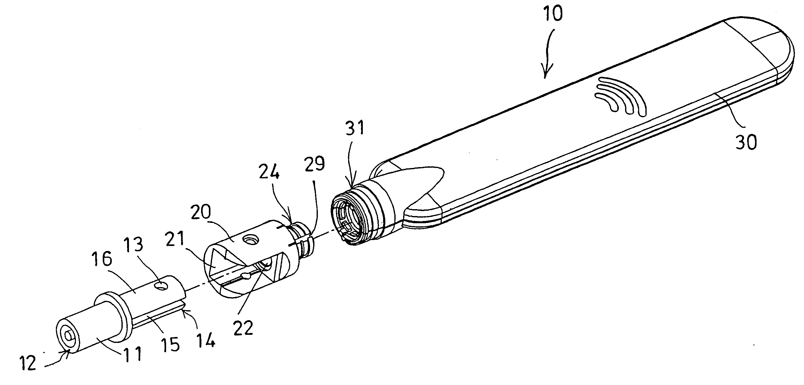
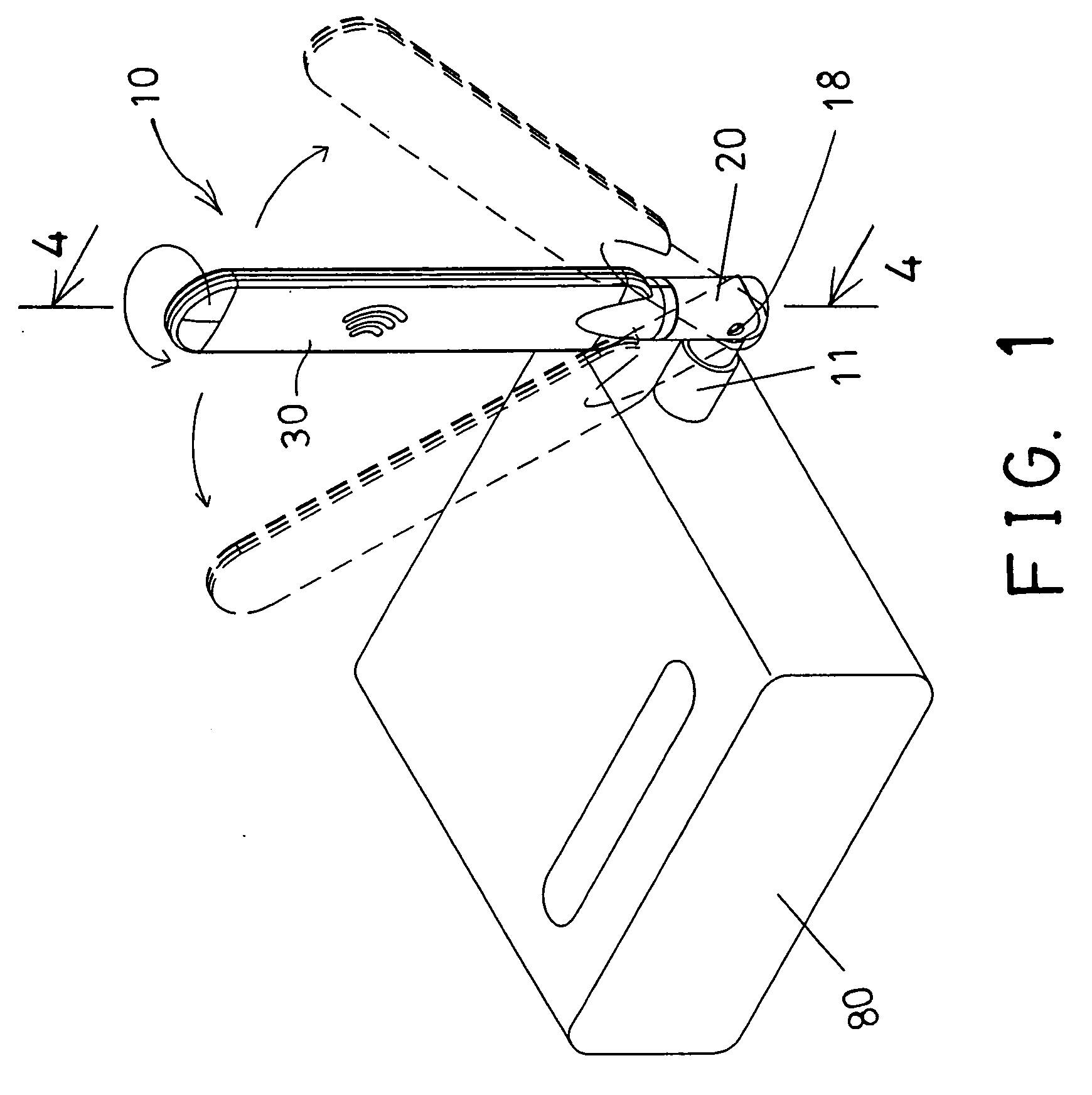
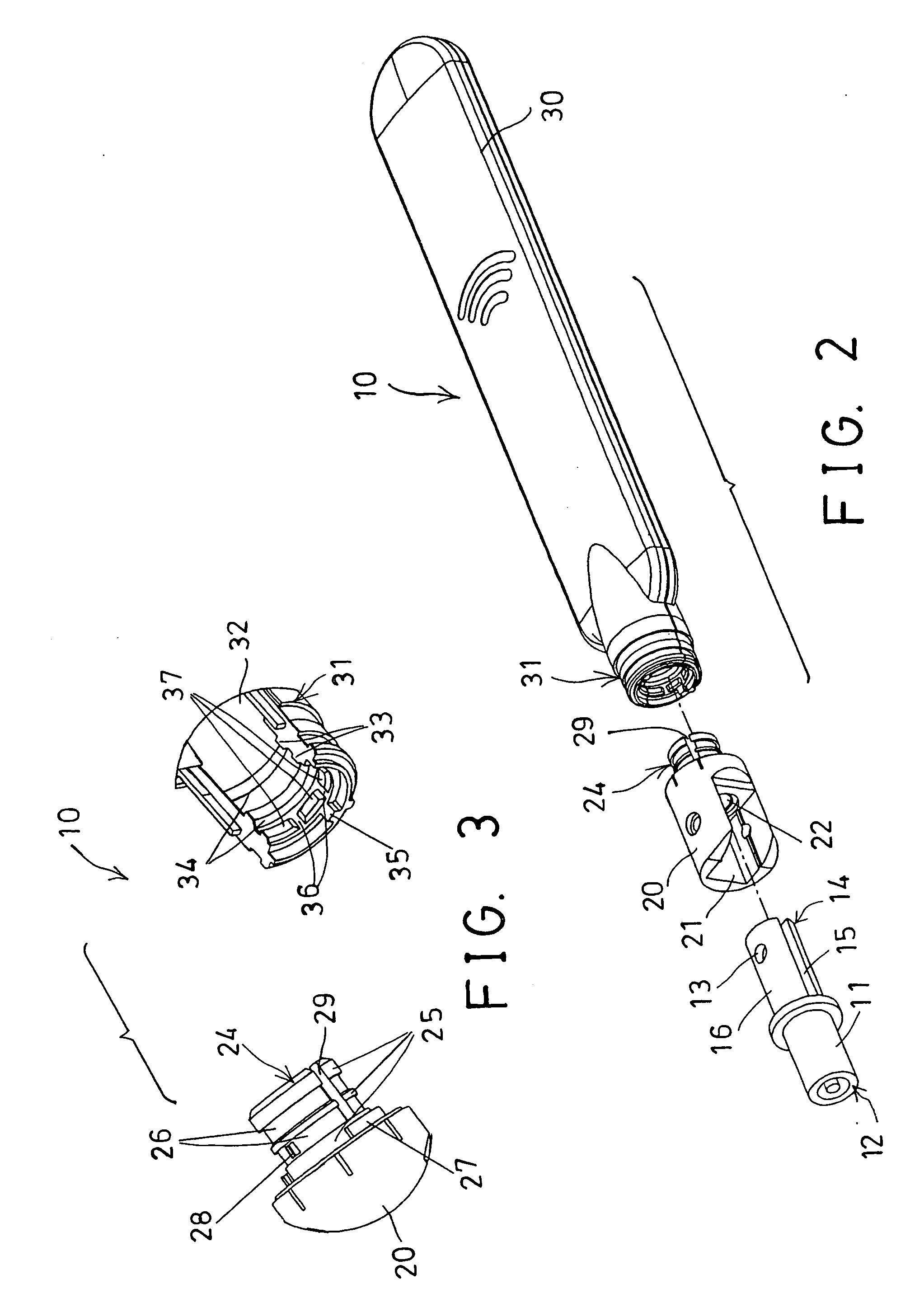
[0020] Referring to the drawings, and initially to FIGS. 1 and 2, an antenna device 10 in accordance with the present invention is provided or arranged for pivotally or rotatably attached to a telecommunicating facility or electric facility or other support objects or devices 80, and comprises a coupler 11 including one end 12 for pivotally or rotatably plugging or attaching to the telecommunicating facility or support device 80, and including an orifice 13 formed in the other end 14 thereof, and preferably further including one or more slots 15 formed in the other end 14 thereof to form one or more spring arms 16.

[0021] A connector 20 includes a chamber 21 formed therein, such as formed in one end thereof, for rotatably receiving or attaching the other end 14 of the coupler 11, and may be pivotally or rotatably coupled to the coupler 11 with a pivot axle 18 (FIG. 1), to allow the connector 20 to be rotated relative to the coupler 11 about the pivot axle 18. The connector 20 includ...


PUM


Abstract

An antenna device includes a coupler rotatably attaching to a support device, a connector rotatably attached to the coupler with a pivot axle and having an extension, and having a stop. An antenna member includes a bore formed in one end for rotatably receiving the extension of the connector. The antenna member includes a stop for engaging with the stop of the connector, and for limiting the antenna member to rotate relative to the connector. The connector includes one or more projections extended into a peripheral groove, and the antenna member includes one or more anchoring members for engaging with the projection of the connector, to position the antenna member to the connector at selected angular position.

Description

BACKGROUND OF THE INVENTION [0001] 1. Field of the Invention [0002] The present invention relates to an antenna device, and more particularly to an antenna device having a rotatable structure for allowing the antenna device to be freely rotated relative to the support object or device to any angular direction. [0003] 2. Description of the Prior Art [0004] Typical antenna devices comprise an antenna housing or member solidly attached or secured onto a telecommunicating facility or the other support objects or devices, and some of the antenna housings or members may include a telescopic structure for selectively extending out of the telecommunicating facility or the other support objects or devices. [0005] For example, U.S. Pat. No. 6,341,217 to Wong discloses one of the typical portable telephones including a shielded transmission antenna that is solidly secured to the typical portable telephone, and may not be extended relative to the typical portable telephone, such that the typica...

Claims


Application Information

Patent Timeline
IPC IPC(8): H01Q1/50
CPCH01Q1/084H01Q9/30H01Q1/40H01Q1/125
Inventor CHAN, YAT TO
Owner JOYMAX ELECTRONICS CO LTD
Why Eureka
Try Eureka