Power transmitting device, power receiving device, authentication/billing proxy device, electrical charging system, power transmitting method, power receiving method and electrical charging method

a technology of power transmission and receiving device, which is applied in secondary cell servicing/maintenance, instruments, transportation and packaging, etc., can solve the problems of communication and processing taking a long time, and achieve the effect of short time of non-contact processing operation, long charging time and low cos

Inactive Publication Date: 2006-12-21
NTT DOCOMO INC
View PDF4 Cites 62 Cited by
  • Summary
  • Abstract
  • Description
  • Claims
  • Application Information

AI Technical Summary

Benefits of technology

[0013] By adapting a power transmitting device like that, charging of a power receiving device can be realized while in non-contact processing operation for the purpose other than charging such as authentication or making a payment. By using a non-contact power transmitting technique and a high-speed bulk electricity storage technique, charging can be rapidly executed bit by bit in a short time of a non-contact processing operation about one to three seconds. That can reduce a load to a user to be attentive to charging.
[0036] The abovementioned systems can provide an environment for a user to use a portable electronic device more natural and suitable to living with fewer loads to the user to be attentive to charging the device. By using the authentication / billing proxy device, the present invention enables a new business such as electric sales by the third party to be developed without increasing a load of bill to a user.

Problems solved by technology

Although Patent Document 1 discloses a basic authenticated electrical charging method and billing method, a charging time cannot be reserved enough in non-contact processing operation time for the purpose other than charging as charging starts after authentication at a server which is at a remote site with much load so that communication and processing take much time.

Method used


Image

  • Power transmitting device, power receiving device, authentication/billing proxy device, electrical charging system, power transmitting method, power receiving method and electrical charging method
  • Power transmitting device, power receiving device, authentication/billing proxy device, electrical charging system, power transmitting method, power receiving method and electrical charging method
  • Power transmitting device, power receiving device, authentication/billing proxy device, electrical charging system, power transmitting method, power receiving method and electrical charging method

Examples


first embodiment

(Description of Electrical Charging System)

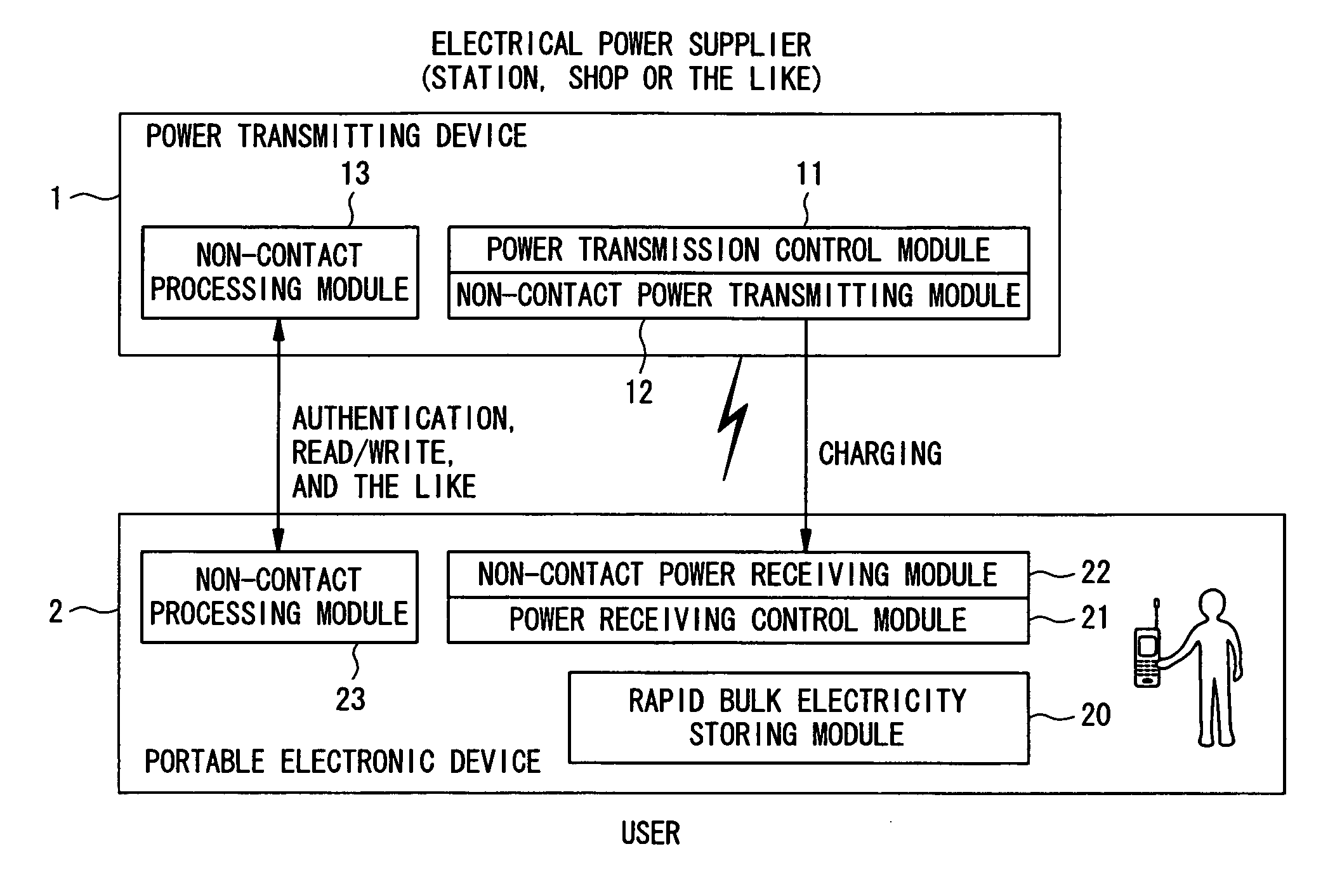
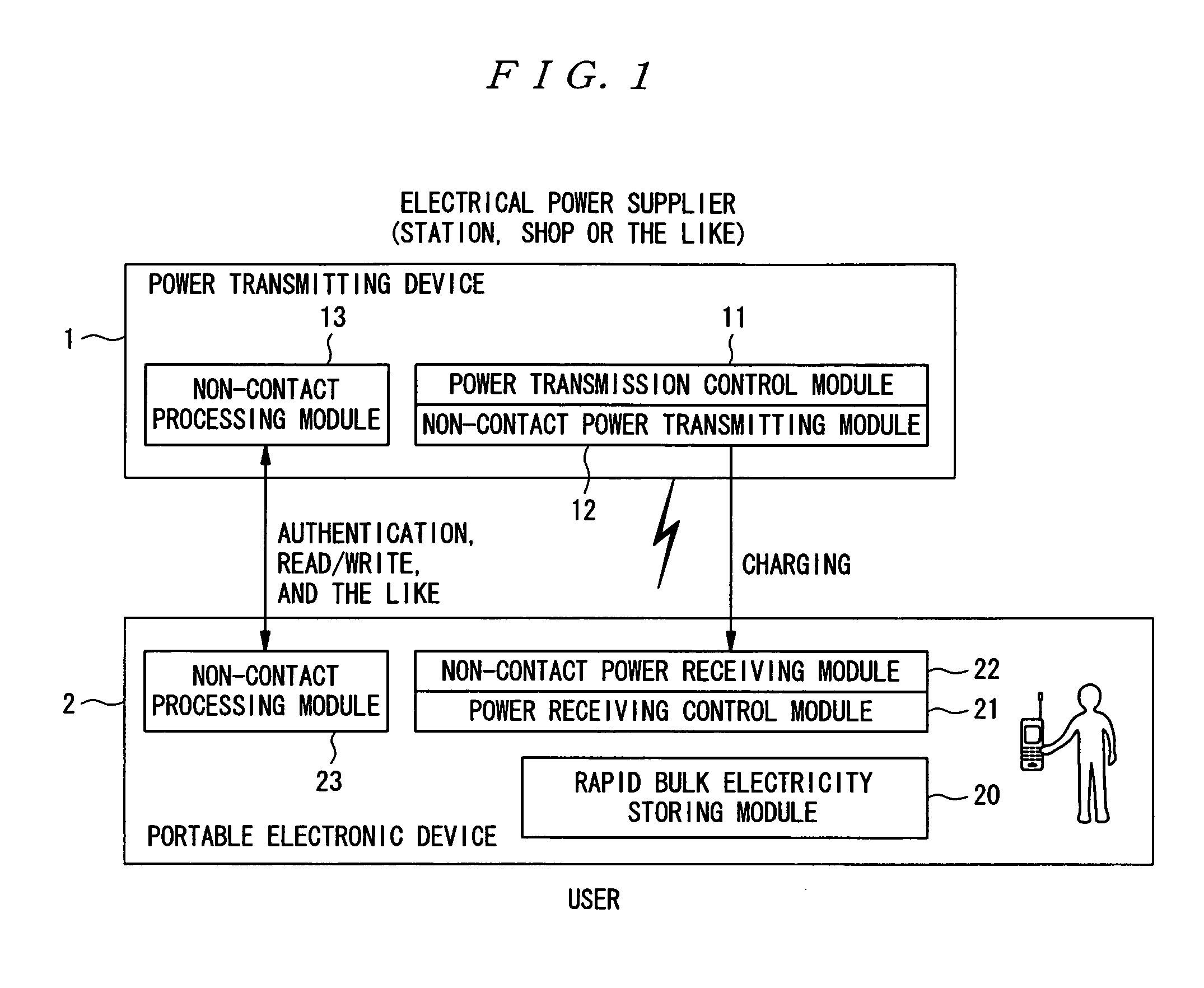
[0109]FIG. 1 is a block diagram showing an exemplary configuration of the first electrical charging system that adopts an electrical charging system according to the present invention. In the figure, the system consists of a power transmitting device 1 that is provided for an electrical power provider side such as a railway station or a shop, and a portable electronic device 2 carried by a user. In the system, the portable electronic device 2 is charged by the power transmitting device 1.

[0110] The power transmitting device 1 consists of a non-contact processing module 13 such as FeliCa (registered trademark) reader, a non-contact power transmitting module 12 and a power transmission control module 11.

[0111] The portable electronic device 2 consists of a non-contact processing module 23 for non-contact processing operation such as FeliCa (registered trademark), a non-contact power receiving module 22 for charging, a power receiving cont...

second embodiment

(Description of the Electrical Charging System)

[0146]FIG. 9 is a block diagram illustrating an exemplary configuration including a first, second, third, fourth, and fifth electrical charging systems that adopt the electrical charging system according to the invention. The electrical charging systems illustrated in the figure consists of the configuration shown in FIG. 1 plus an authentication / billing proxy device 3 that is provided in an authentication / billing agent such as a cellular phone service provider. In this system, the portable electronic device 2 is charged by the power transmitting device 1 and billed by the authentication / billing proxy device 3 as necessary.

[0147] The power transmitting device 1 includes a non-contact processing module 13 such as a FeliCa (a registered trademark) reader, anon-contact power transmitting module 12, and a power transmission control module 11. The portable electronic device 2 includes a non-contact processing module 23 for non-contact pro...

third embodiment

(Charging Between Portable Electronic Devices)

[0318] If a portable electronic device keeps a function corresponding to the abovementioned power transmitting device (such as a power transmitting function), the portable electronic device can be an electrical power supplier. That is, a portable electronic device can transmit power to charge the other portable electronic device.

[0319] When charging is executed between portable electronic devices, the same processing as that described with reference to FIG. 9 to FIG. 32 is executed. In such cases, a portable electronic device functions as a power transmitting device in the figures. When either of the portable electronic devices works as an authentication / billing proxy device or makes a payment with electronic money, however, that device may be restricted. For example, such a portable electronic device needs to be able to communicate with an authentication / billing proxy device and also needs to be registered previously as a power trans...


PUM

PropertyMeasurementUnit
timeaaaaaaaaaa
charging timeaaaaaaaaaa
transmitting poweraaaaaaaaaa

Abstract

To realize charging while in non-contact processing operation for the purpose other than charging. An approach of a portable electronic device 2 with a rapid bulk electricity storing module 20, which is a chargeable power source, is detected at the side of a power transmitting device 1, and power transmission for charging the rapid bulk electricity storing module 20 is executed in response to the detection of the approach. A power source can be charged in operation for non-contact authentication which is executed when a device approaches an authentication device.

Description

BACKGROUND OF THE INVENTION [0001] 1. Field of the Invention [0002] The present invention relates to a power transmitting device, a power receiving device, an authentication / billing proxy device, an electrical charging system and an electrical charging method, more specifically to a power transmitting device, a power receiving device, an authentication / billing proxy device, an electrical charging system, a power transmitting method, a power receiving method and an electrical charging method which are used in charging a battery provided for a portable electronic device such as a cellular phone, a notebook PC (Personal Computer) and a PDA (Personal Digital Assistant). [0003] 2. Description of the Related Art [0004] Non-contact power transmitting techniques, non-contact processing techniques and high-speedbulk electricity storage techniques have been known. For example, as a non-contact power transmitting technique, a non-contact power transmitting module is known (for example, see “th...

Claims


Application Information

Patent Timeline
Patent Type & Authority Applications(United States)
IPC IPC(8): G06F17/00H02J7/02G06Q30/04G06Q30/06G06Q50/00H01M10/44H02J7/00H02J17/00
CPCG06Q40/00Y04S10/58H02J7/025H02J7/0004H02J7/00036H02J7/00047Y04S10/50H02J50/80H02J50/10
Inventor OCHI, DAISUKEKINNO, AKIRAHAGINO, HIROAKIHASHIDA, NAOKIYOSHIKAWA, TAKASHI
Owner NTT DOCOMO INC
Why Eureka
Try Eureka