Apparatus and methods for creation of down hole annular barrier

a technology of annular barrier and well bore, which is applied in the direction of sealing/packing, borehole/well accessories, survey, etc., can solve the problems of not preventing, cave-in or well bore fluid control becoming potential problems, and operations requiring cessation of drilling operations, so as to add redundancy to the fluid barrier seal mechanism

a technology of annular barrier and well bore, which is applied in the direction of sealing/packing, borehole/well accessories, survey, etc., can solve the problems of not preventing, cave-in or well bore fluid control becoming potential problems, and operations requiring cessation of drilling operations, so as to add redundancy to the fluid barrier seal mechanism

US20070062694A1Inactive Publication Date: 2007-03-22WEATHERFORD TECH HLDG LLC

Image

  • Apparatus and methods for creation of down hole annular barrier
  • Apparatus and methods for creation of down hole annular barrier
  • Apparatus and methods for creation of down hole annular barrier

Examples


Embodiment Construction

[0024] The invention generally relates to methods and apparatus for creating an annular barrier about a casing shoe.

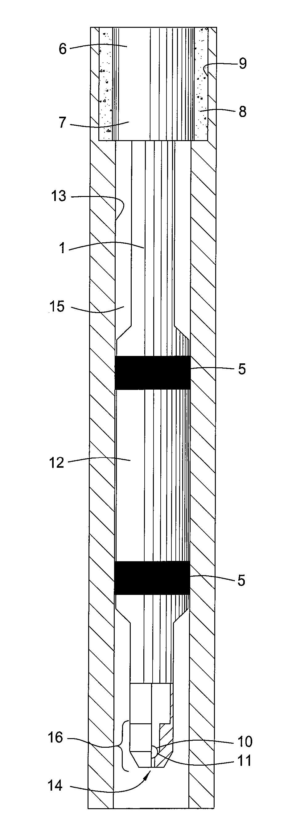
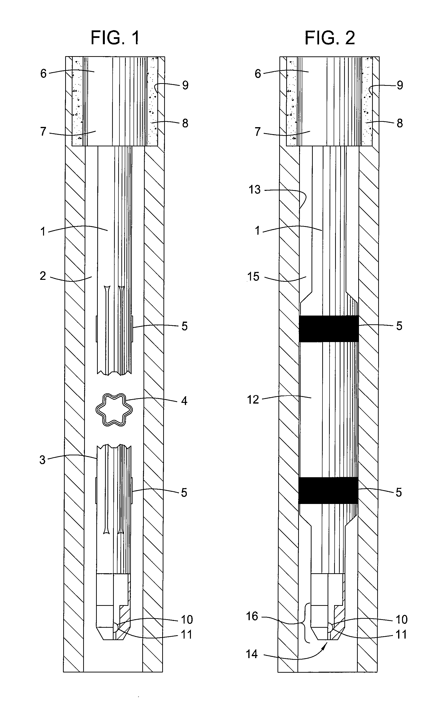
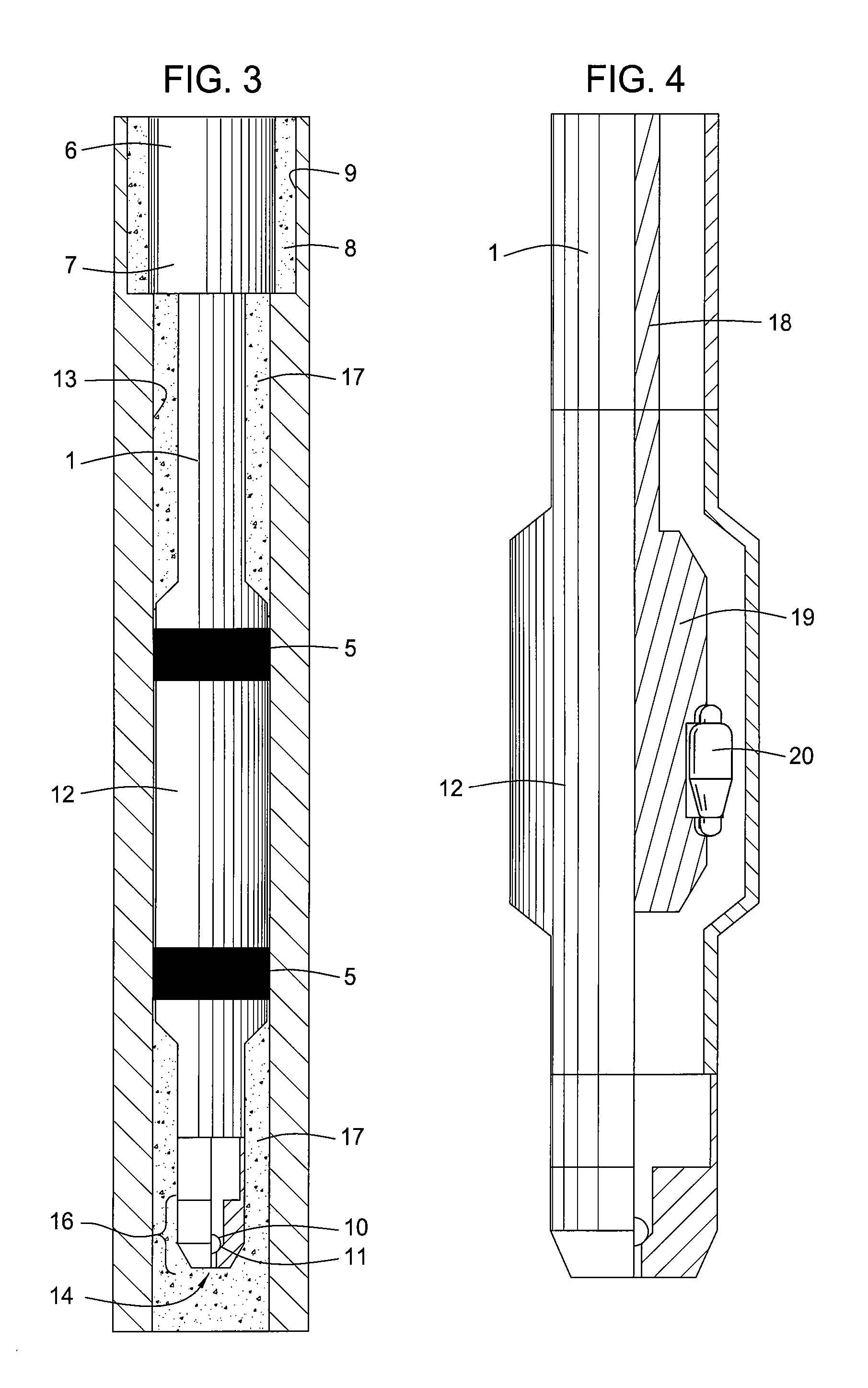
[0025] The embodiments of FIGS. 1, 2 and 3 are shown deployed beneath a previously and conventionally installed casing 6 in a previously drilled well bore 9. The annular barrier between the conventional shoe portion 7 of the previously installed casing 6 and the previously drilled well bore 9 is only cement 8.

[0026]FIG. 1 shows a casing string 1 deployed in a sectioned well bore 2 where the casing string 1 includes an unexpanded folded expandable portion 3 and a cross-section thereof 4 and having two elastomeric coated regions 5 about a perimeter of the folded portion 3. The well bore 2 is drilled following the drilling of the well bore 9, running of the casing 6, placing of the cement 8 and shoe testing the barrier formed by the cement 8. The casing string 1 is lowered from the surface into the well bore 2 and a ball 10 is placed in the interior of the casing 1 and ...


PUM


Abstract

Methods and apparatus are provided for performing an expedited shoe test using an expandable casing portion as an annular fluid barrier. Such an expandable annular fluid barrier may be used in conjunction with cement if so desired but cement is not required. Further provided are methods and apparatus for successfully recovering from a failed expansion so that a shoe test can be completed without replacement of the expandable casing portion.

Description

CROSS-REFERENCE TO RELATED APPLICATION [0001] This application claims benefit of co-pending U.S. Provisional Patent Application Ser. No. 60 / 701,720, filed on Jul. 22, 2005, which application is incorporated herein by reference in its entirety.BACKGROUND OF THE INVENTION [0002] 1. Field of the Invention [0003] Embodiments of the invention generally relate to methods and apparatus for creating an annular barrier in a well bore. More particularly, the invention relates to methods and apparatus for isolating at least a portion of a well bore from at least another portion of the well bore. [0004] 2. Description of the Related Art [0005] As part of the well bore construction process, a hole or well bore is typically drilled into the earth and then lined with a casing or liner. Sections of casing or liner are threaded together or otherwise connected as they are run into the well bore to form what is referred to as a “string.” Such casing typically comprises a steel tubular good or “pipe” h...

Claims


Application Information

Patent Timeline
22 Mar 2007
Publication
US20070062694A1
IPC
E21B43/10; E21B47/10
CPC
E21B33/128; E21B47/0005; E21B43/103; E21B47/005; E21B21/10; E21B29/00
Inventors
RING, LEV; COOK, ROBERT LANCE