Synthetic resin heat-resistant bottle type container

Active Publication Date: 2007-04-05
YOSHINO KOGYOSHO CO LTD
View PDF10 Cites 15 Cited by
  • Summary
  • Abstract
  • Description
  • Claims
  • Application Information

AI Technical Summary

Benefits of technology

[0015] A resin is more effectively stretched during blow molding when the at least one convex portion comprises two or more convex portions aligned in a stepwise configuration on the wall face of the pressure reduction absorbing panel, and/or when a convex portion is formed at a wall face of the panel having ridge lines in an inverted V-shaped or having a substantially trapezoidal shape with a lower side longer than an upper side. This assuredly restricts occurrence of resin accumulation, whitening, and the like, and molds the container into a desired wall thickness.
[0016] Further, it is desirable that the pressure reduction absorbing panels each have a border line bulged toward the container bottom part along the wall face of the applicable pressure reduction absorbing panel. Although the boundary between each pressure reduction absorbing panel and the body part at the upper side of the panel is an area where a resin accumulation

Problems solved by technology

Thus, in blow molding such a bottle, it has been likely that smooth stretching of a resin is obstructed at mold surface portions corresponding to the concave and c

Method used


Image

  • Synthetic resin heat-resistant bottle type container
  • Synthetic resin heat-resistant bottle type container
  • Synthetic resin heat-resistant bottle type container

Examples


Embodiment Construction

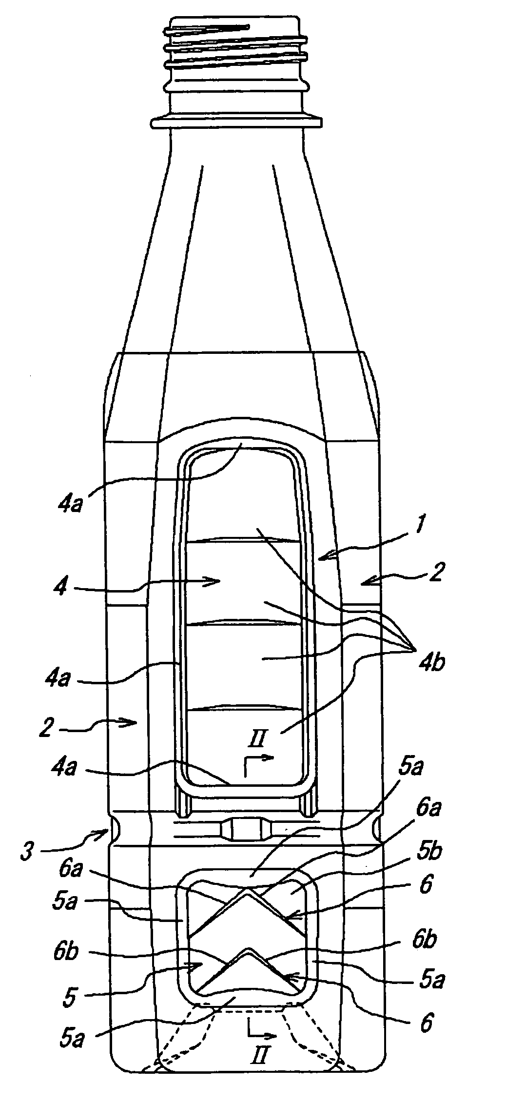
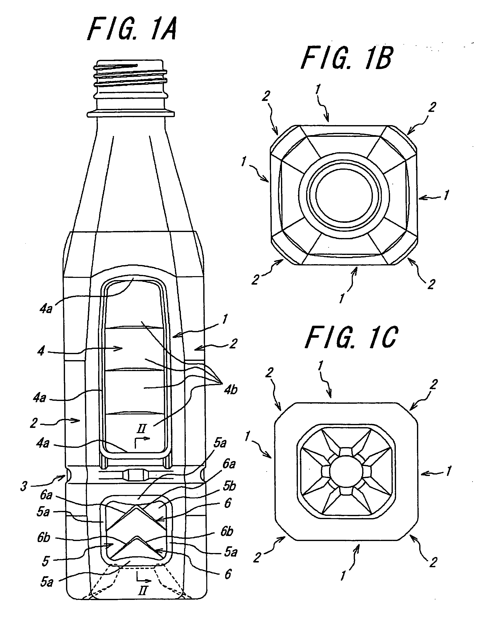
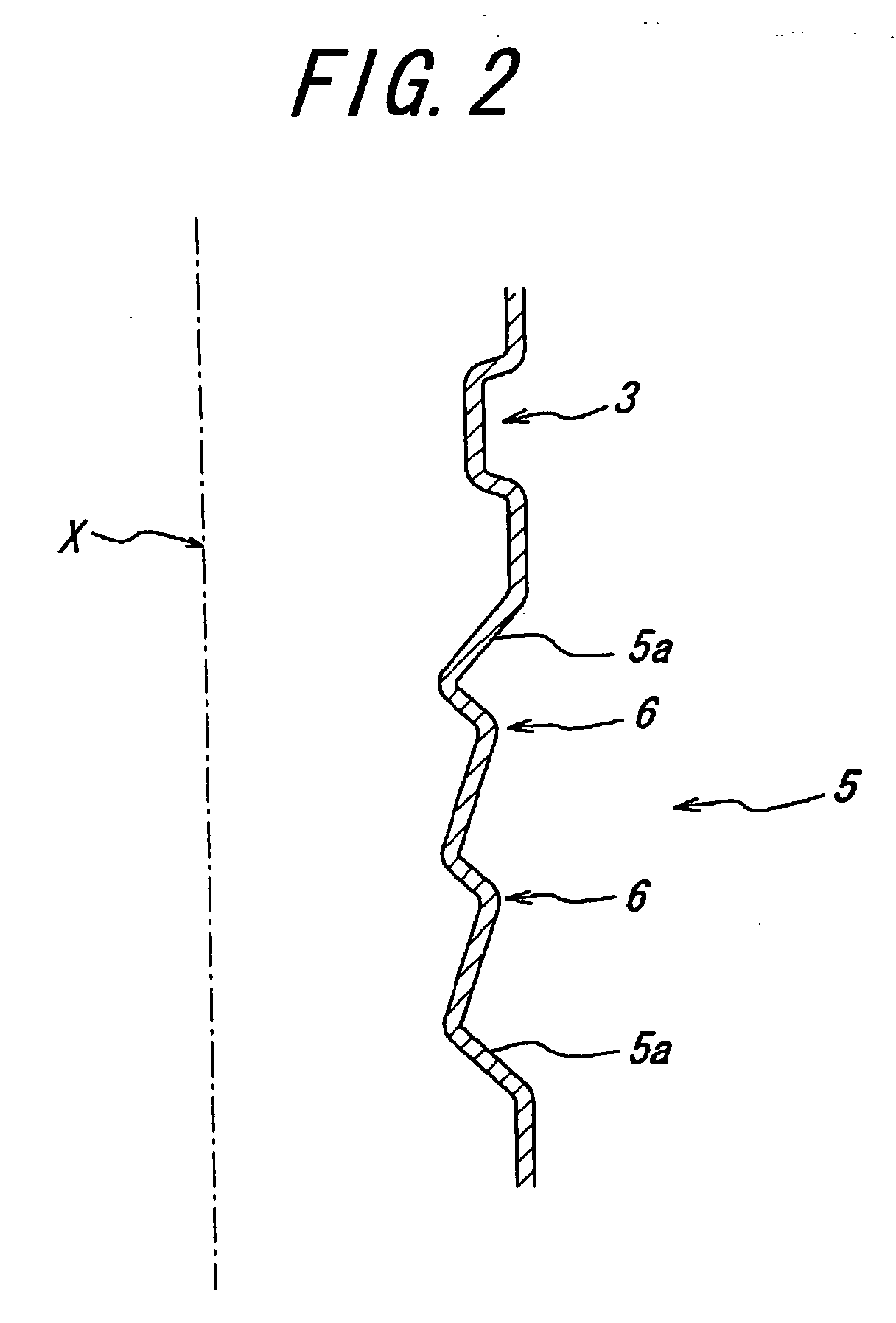
[0026]FIGS. 1A, 1B and 1C show an embodiment of a synthetic resin heat-resistant container according to the present invention constituted as a slender rectangular bottle having a filling capacity of about 350 milliliter and a circumferential draw ratio of 2.8 or less. Reference numerals 1 designate wall faces constituting a container body part. Reference numerals 2 designate corner portions connecting end portions of wall faces 1 to similarly constitute the container body part. Reference numeral 3 designates a groove portion provided around the container body part. Reference numerals 4 designate upper panels provided at the wall faces 1 above the groove portion 3 so as to absorb pressure reduction. Reference numerals 5 designate lower panels provided at the wall faces 1 below the groove portion 3 so as to absorb pressure reduction.

[0027] The upper panels 4 and lower panels 5 are connected to the container body part through sidewalls 4a and 5a directed toward an inside of the contai...


PUM

PropertyMeasurementUnit
Angleaaaaaaaaaa
Angleaaaaaaaaaa
Ratioaaaaaaaaaa

Abstract

A slender synthetic resin heat-resistant bottle type container having a circumferential draw ratio of 2.8 or less, for example, comprises at least one pressure reduction absorbing panel (5) provided at a container body part, wherein the pressure reduction absorbing panel is provided with at least one convex portion (6) having a width larger at a lower side than at an upper side as viewed in a circumferential direction of the container. Alternatively, each pressure reduction absorbing panel has a border line bulged toward a container bottom part. This causes a resin to be smoothly stretched even at mold surface portions corresponding to concave and convex portions of a container body part surface upon blow molding. These avoid a defective appearance of the container and do not adversely affect heat resistance thereof.

Description

[0001] This application is the U.S. National Stage of PCT / JP2004 / 017419 filed Nov. 24, 2004, which claims priority from Japanese Patent Application No. JP2003-395564 filed Nov. 26, 2003, and Japanese Patent Application No. JP2004-339150 filed Nov. 24, 2004, the entire disclosures of which are incorporated herein by reference there o in their entireties. [0002] 1. TECHNICAL FIELD [0003] The present invention relates to a synthetic resin heat-resistant bottle type container, and particularly to a bottle type container having a plurality of pressure reduction absorbing panels at a body part. [0004] 2. Background Art [0005] In a synthetic resin heat-resistant bottle having a plurality of pressure reduction absorbing panels at a body part, concave and convex portions are formed on a body part surface to delimit the pressure reduction absorbing panels, respectively. Thus, in blow molding such a bottle, it has been likely that smooth stretching of a resin is obstructed at mold surface port...

Claims


Application Information

Patent Timeline
IPC IPC(8): B65D90/02B29C49/06B65D1/02
CPCB29C49/06B65D1/0223B65D2501/0081B29C2949/0715B65D1/02B65D1/26B65D1/00
Inventor TANAKA, TOSHIMASANAKAYAMA, TADAYORITABATA, SHINICHIIIZUKA, TAKAO
Owner YOSHINO KOGYOSHO CO LTD
Why Eureka
Try Eureka