Liquid tank and ink jet printing apparatus

a liquid tank and ink jet printing technology, applied in the direction of instruments, transportation and packaging, packaging, etc., can solve the problems of difficult to increase the accuracy with which to determine the remaining amount of ink, disadvantages in cost, space and ink housing efficiency, etc., to reduce the size of the ink jet printing apparatus and the size of the liquid tank. , the effect of easy reduction of the size of the liquid tank

Inactive Publication Date: 2007-07-12
CANON KK
View PDF26 Cites 14 Cited by
  • Summary
  • Abstract
  • Description
  • Claims
  • Application Information

AI Technical Summary

Benefits of technology

[0029] In order to avoid affecting the quantity of light reciprocating within the liquid accommodating chamber and entering the light receiving section, the liquid tank, mounted in the printing apparatus, is desirably configured so as to prevent external light from entering the tank.
[0030] According to the present invention, it is possible to sense the a

Problems solved by technology

However, it is not preferable for a particularly small-sized ink tank to be provided with a detecting mechanism that is disadvantageous in cost, space, and ink housing efficiency.
Further, it is not preferable to provide a

Method used


Image

  • Liquid tank and ink jet printing apparatus
  • Liquid tank and ink jet printing apparatus
  • Liquid tank and ink jet printing apparatus

Examples


first embodiment

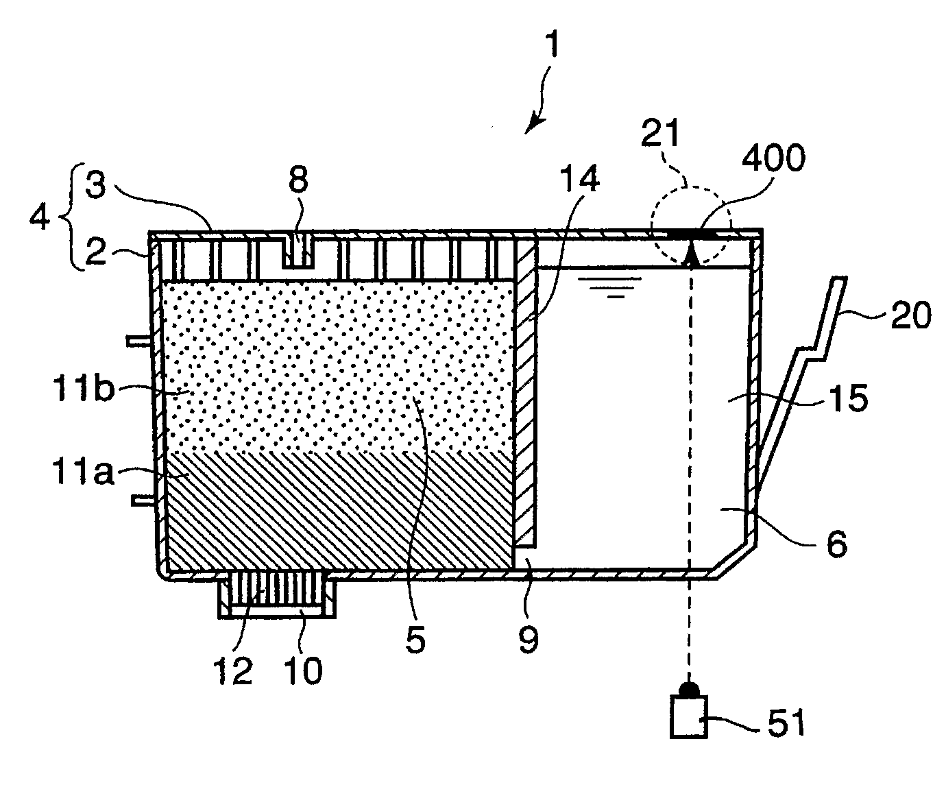
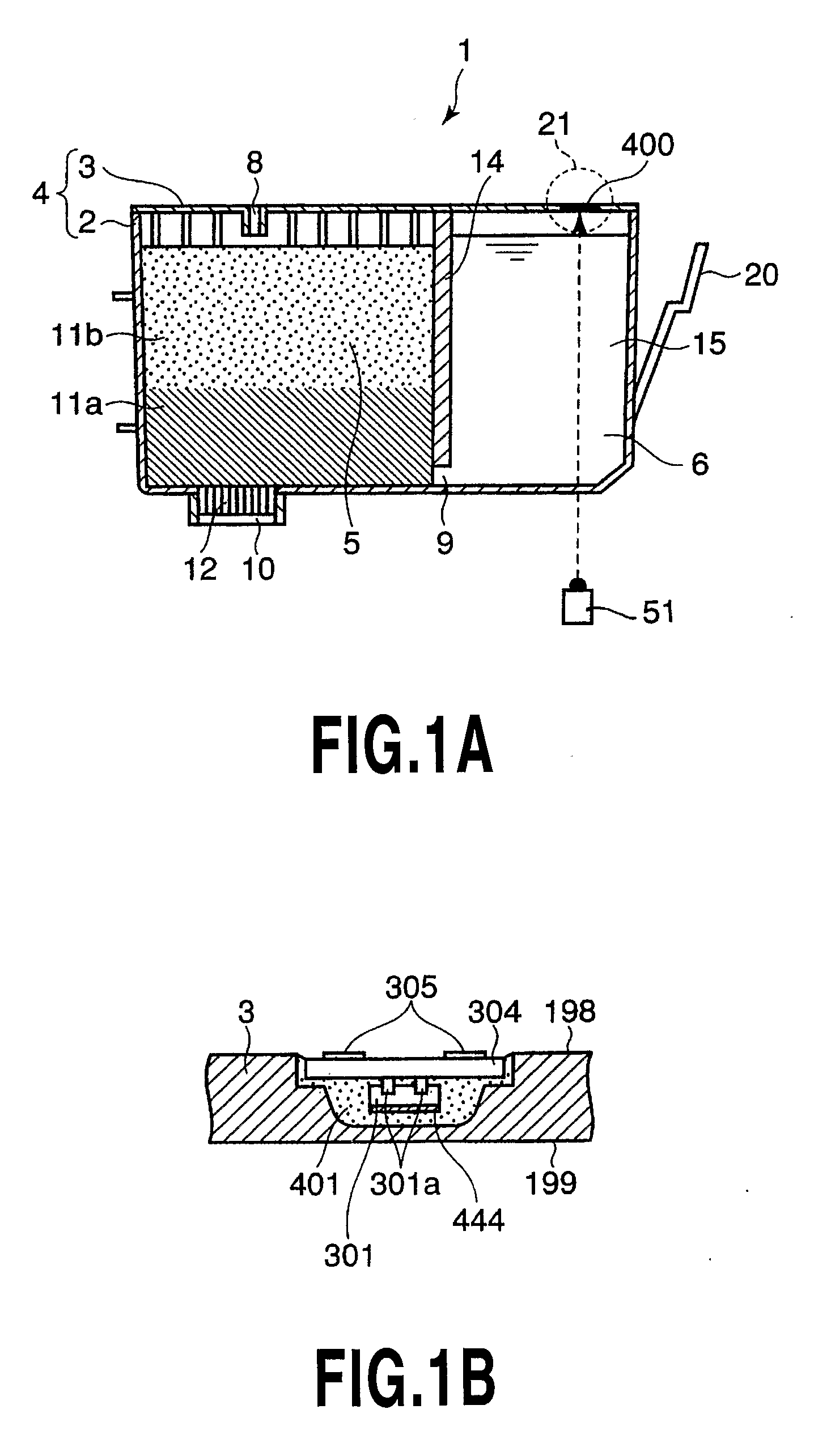
[0046]FIG. 1A is a sectional view schematically showing the configuration of an ink tank (liquid tank) 1 according to a first embodiment of the present invention.

[0047] In the ink tank 1, a housing 4 composed of a container 2 and a cover 3 is partitioned into two independent spaces using a partitioning wall 14; the spaces are in communication only via a communication portion 9 in the lower part of the partitioning wall 14. One of the two spaces is a negative pressure generating member housing chamber 5 in which two types of negative pressure generating members 11a and 11b are stacked and housed. The other space is an ink accommodating chamber (liquid accommodating chamber) 6.

[0048] The ink tank 1 is detachably installed on a carriage (not shown) in an ink jet printing apparatus main body using a lever 20; the carriage can be reciprocated. An ink supply port 10 is formed in a bottom wall of the negative pressure generating member accommodating chamber 5; an ink lead-out member 12 i...

second embodiment

[0077]FIG. 9A is a schematic diagram of an ink remaining amount sensing module provided in an ink tank according to a second embodiment of the present invention.

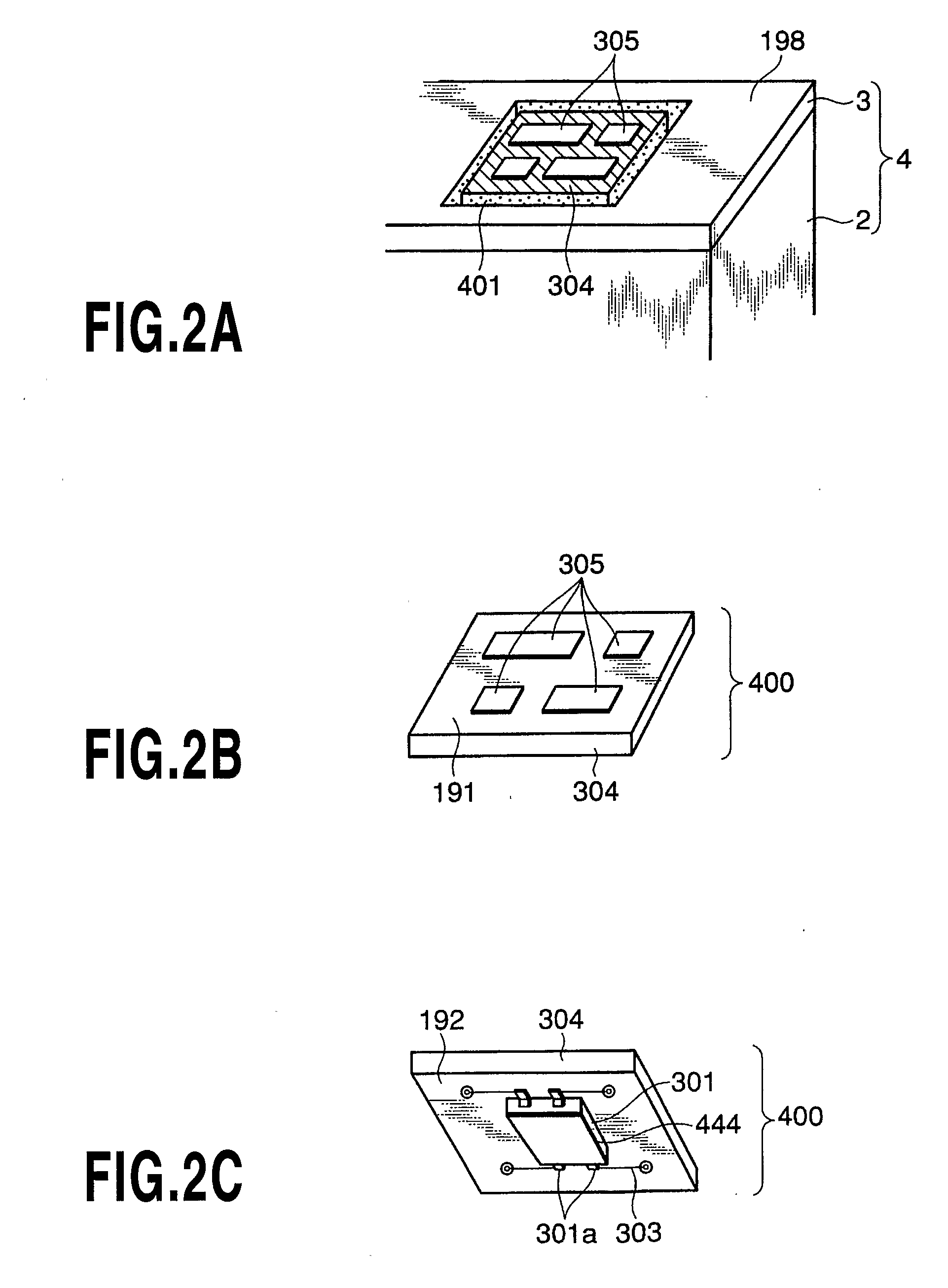
[0078] In the present embodiment, in contrast to the optical reflector 444 according to the first embodiment, an optical reflector 301c is formed utilizing a lead frame used to form a lead terminal 301a in mold-packaging the information storage element 301. Solder plating does not provide a high reflectance, so that the lead frame is desirably plated with gold. The optical reflector may be an aluminum reflection film, which exhibits a high reflectance of about 90% for light over a wide wavelength band. However, gold exhibits a reflectance of less than 40% in a near ultraviolet region but a high reflectance of 97 to 98% in an infrared region. Accordingly, gold can be effectively utilized as an optical reflector. Further, the gold reflector is desirable because it is more resistant to corrosion than the aluminum reflector.

third embodiment

[0079]FIG. 9B is a schematic diagram of an ink remaining amount sensing module provided in an ink tank according to a third embodiment of the present invention.

[0080] In the present embodiment, an optical reflector 303a is composed of a wiring member formed in a wide area of a wiring pattern formed on a printed circuit board as the support substrate 304. As in the case of the second embodiment, the wiring member is desirably plated with gold. However, a copper pattern used for common wiring members may be used provided that a sealing adhesive can be used to form a barrier against external environments. Further, measures are desirably taken for corrosion, migration, and the like. However, if it is undesirable to increase costs by employing gold plating, the copper pattern may be plated with nickel. In this case, a reflectance (about 70%) is obtained which is comparable to that of the stainless steel mirror shown in the first embodiment.


PUM


Abstract

There is provided a liquid tank having a liquid remaining amount sensing module that makes it possible to reliably determine that the amount of ink has reached a predetermined value, in spite of its simple and compact configuration. In the ink tank, an information storage element and a module are provided on a ceiling portion of an ink accommodating chamber directly accommodating ink; the module having an optical reflector that faces downward in a vertical direction. A housing of the ink tank is composed of a transparent resin. Infrared light from an external light emitting section is incident on the optical reflector. The reflected light is received by a light receiving section and then, the quantity of light is measured.

Description

TECHNICAL FIELD [0001] The present invention relates to a liquid tank (ink tank) accommodating a liquid such as ink which is supplied to a print head (ink jet print head) that ejects the liquid for printing, and an ink jet printing apparatus in which the liquid tank is mounted for printing. BACKGROUND ART [0002] Japanese Patent No. 2951818 discloses a known ink tank provided in an ink jet printing apparatus to supply a liquid such as ink (simply referred to as “ink” below) to an ink jet print head that ejects the ink in order to print on a print medium. FIG. 13A shows an ink tank 501 as an example utilizing the above configuration. [0003] In the ink tank 501, a housing 504 composed of a container 502 and a cover 503 is partitioned into two spaces using a partitioning wall 514 having a communication portion 509. One of the two spaces is an ink accommodating chamber 506 which is closed except for the communication portion 509 of the partitioning wall 514 and which directly houses ink ...

Claims


Application Information

Patent Timeline
IPC IPC(8): B41J2/195B05C5/00B05C11/10B41J2/175B65D83/00
CPCB41J2002/17573B41J2/17566
Inventor YAMAMOTO, HAJIME
Owner CANON KK
Why Eureka
Try Eureka