Light coupling apparatus

a technology of coupling apparatus and light, applied in the direction of instruments, optical waveguide light guides, optics, etc., can solve the problems of inflexible incident angle of light, failure of light coupling, poor quality white light, etc., and achieve the effect of convenient assembly and configuration

Active Publication Date: 2007-07-12
DELTA ELECTRONICS INC
View PDF7 Cites 4 Cited by
  • Summary
  • Abstract
  • Description
  • Claims
  • Application Information

AI Technical Summary

Benefits of technology

[0013]The primary object of this invention is to provide a light coupling apparatus for use in an optical equipment, provided for coupling a plurality of different incident lights from different light sources by employing at least two medium with different refractive indexes to totally or partially proceed with total reflection, and then, coupling the lights toward a predetermined single direction or directions. The light coupling apparatus is convenient to assemble and configure. It can also fit many different kinds of optical devices. In order to achieve the above-mentioned object, the light coupling apparatus comprises a first medium having a first refractive index (n1) and a second medium, having a second refractive index (n2), wherein n1 is greater than n2, and a 1-2 interface is formed between the second medium and the first medium. A first light source provides a first incident light, totally reflecting onto the 1-2 interface from the first medium and emitting in a coupling direction from the light coupling apparatus. A second light source provides a second incident light, refracting through the 1-2 interface from the second medium into the first medium, and emitting in the coupling direction from the light coupling apparatus.

Problems solved by technology

If the incident directions are at different angles, either light coupling will fail or the white light will be of poor quality.
The X-plate may be a simpler design in comparison with the X-cube; however, it bears disadvantages that the incident lights must be divided into different single colors beforehand, and the incident angles of light is inflexible.
Unfortunately, in this design, the lights must be divided beforehand.
In addition, the incident angle can not be adjusted flexibly.
In addition to the aforementioned limits of the three known designs, it is difficult to couple more than three incident lights into a white light.
Although this apparatus overcomes the need to divide the lights beforehand, it is still not flexible enough to couple more than two incident lights.

Method used


Image

  • Light coupling apparatus
  • Light coupling apparatus
  • Light coupling apparatus

Examples


first embodiment

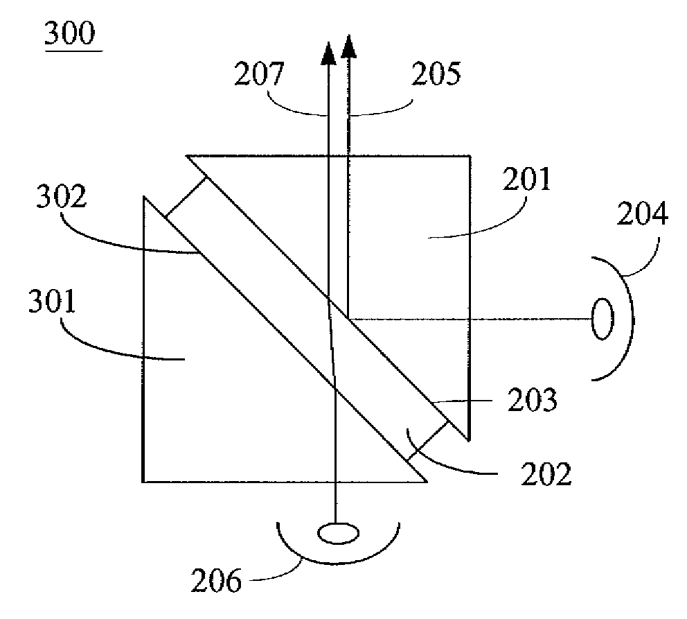
[0025]the present invention, as shown in FIG. 2, is a light coupling apparatus 200 for use in an optical equipment. The apparatus is provided for coupling two different incident lights from two different light sources. The light coupling apparatus 200 comprises: a first medium 201 which has a first refractive index n1 and a second medium 202 which has a second refractive index n2. The index n1 is greater than n2, and a 1-2 interface 203 is formed between the second medium 202 and the first medium 201. This would be the condition that the so-defined total reflection applies. A first light source 204 provides a first incident light 205. The first incident light 205 totally reflects onto the 1-2 interface 203 from the first medium 201, and emits in a coupling direction from the light coupling apparatus 200. A second light source 206 provides a second incident light 207. The second incident light 207 refracts through the 1-2 interface 203 into the first medium 201 from the second medium...

second embodiment

[0033]Furthermore, an alternative of the second embodiment is to add some other media (e.g., a third medium 503) to the aforementioned apparatus, which is shown in FIG. 5. Some of the reference numerals in FIG. 4 are adopted in FIG. 5 for convenience. In particular, the similarities, as shown in FIG. 4, include the light path of the first incident light 406 of the first light source 405 and its total reflection occurring on the 1-2 interface 403, as well as the light path of the second incident light 408 of the second light source 407 through the boundary 404 and onto the 1-2 interface 403. Therefore, the repetitive descriptions are omitted. The light coupling apparatus 500 further comprises: a third light source 501 that provides a third incident light 502; and a third medium 503, which has a third refractive index n3, wherein n3>n2. A 2-3 interface 504 is formed between the second medium 402 and the third medium 503. The 2-3 interface 504 comprises a 2-3 boundary 505. The third in...

third embodiment

[0036]As mentioned above, an alternative of the third embodiment is applicable. The light coupling apparatus 600 further comprises, at the least, a fourth light source 603, which provides, at the least, an incident light 604. The incident light 604 totally reflects onto an interface (i.e. a 0-3 interface 607) formed by air and the third medium 503. This light then totally reflects onto the 2-3 interface 504 from the third medium 503, and then emits in the coupling direction from the third medium 503. There are two other similar occasions of the fourth light source 603 shown in FIG. 6 as well for reference.

[0037]It can be further derived from FIG. 6 that the third embodiment further comprises a plurality of fourth light sources (not shown) to provide a plurality of fourth incident lights (not shown). Each of the fourth incident lights totally reflects onto the 1-2 interface 403 and the 2-3 interface 504 from the first medium 401 and the third medium 503, respectively, emitting in a c...


PUM


Abstract

A light coupling apparatus for use in an optical equipment is provided. The light coupling apparatus is used to couple a plurality of different incident lights from different light sources into a light that emits in a substantial single outward direction.

Description

[0001]This application claims priority based on Taiwan Patent Application No. 095101079 filed on Jan. 11, 2006.CROSS-REFERENCES TO RELATED APPLICATIONS[0002]Not applicable.BACKGROUND OF THE INVENTION[0003]1. Field of the Invention[0004]The present invention relates to a light coupling apparatus for use in an optical equipment. In particular, it relates to an apparatus for coupling a plurality of different incident lights from different light sources into lights in a substantial single outward direction or in a plurality of different outward directions.[0005]2. Descriptions of the Related Art[0006]In recent years, the market for optical equipment has developed significantly, improving the quality of related products as well. For example, related optical coupling apparatuses, such as an X-cube, and an X-plate, are widely used and have been dramatically improved. Still, providers are continuing to improve the quality of optical apparatuses to get better light coupling quality.[0007]Tak...

Claims


Application Information

Patent Timeline
Patent Type & Authority Applications(United States)
IPC IPC(8): G02B6/10
CPCG02B27/143G02B5/04
Inventor WU, YU-HSI
Owner DELTA ELECTRONICS INC
Why Eureka
Try Eureka