Initial velocity accelerating tube

Inactive Publication Date: 2012-04-19
J B UNICORN
View PDF33 Cites 5 Cited by
  • Summary
  • Abstract
  • Description
  • Claims
  • Application Information

AI Technical Summary

Benefits of technology

[0007]When the initial velocity accelerating tube of the present invention is mounted on the toy gun, the inner pipe has the end connected to the connection member to hold against the front end of the barrel of the toy gun by the elastic force of the elast

Problems solved by technology

However, in consideration of reality and carrying, the length of the toy gun is limited.
In these days, the len

Method used


Image

  • Initial velocity accelerating tube
  • Initial velocity accelerating tube
  • Initial velocity accelerating tube

Examples


Embodiment Construction

[0013]Embodiments of the present invention will now be described, by way of example only, with reference to the accompanying drawings.

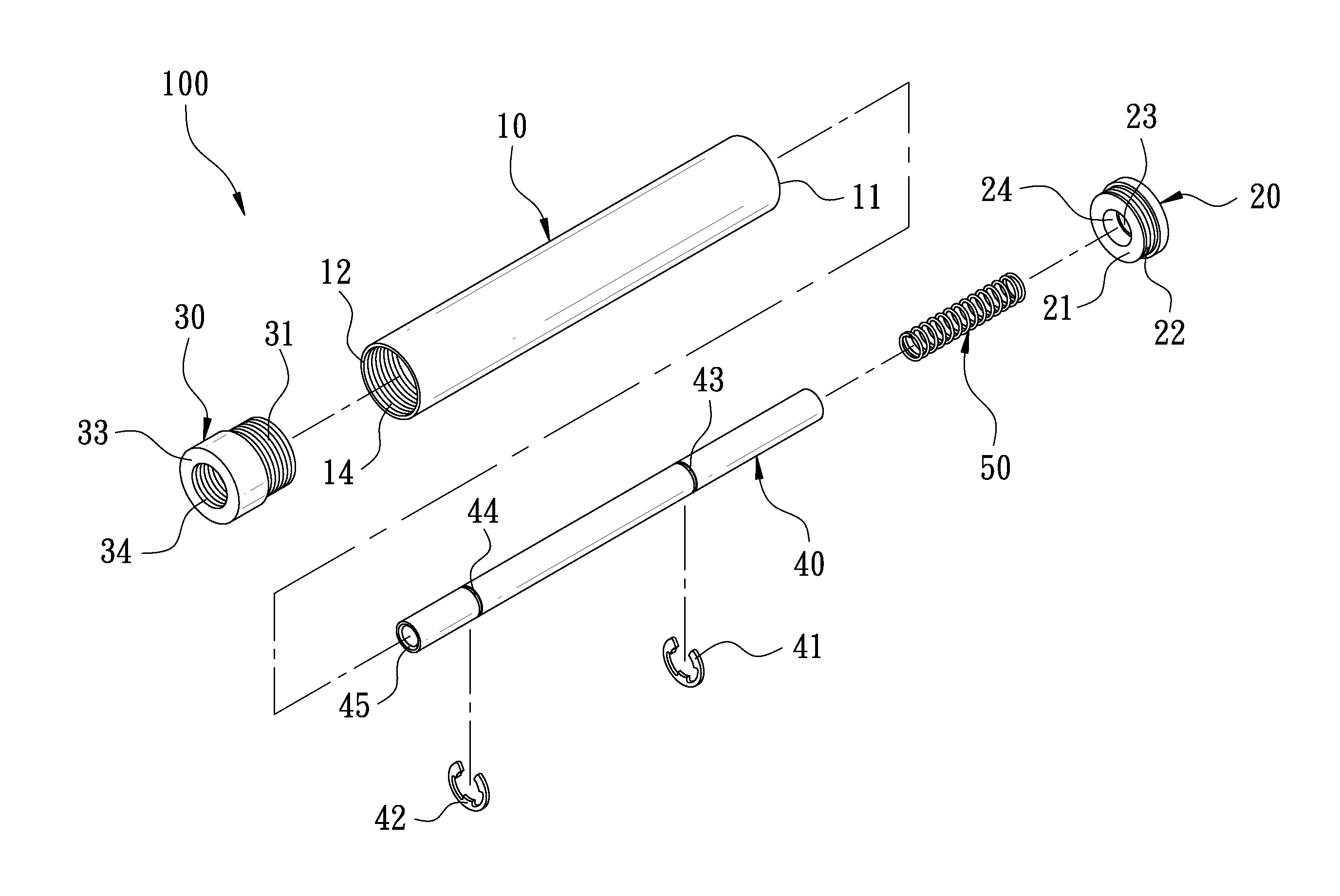
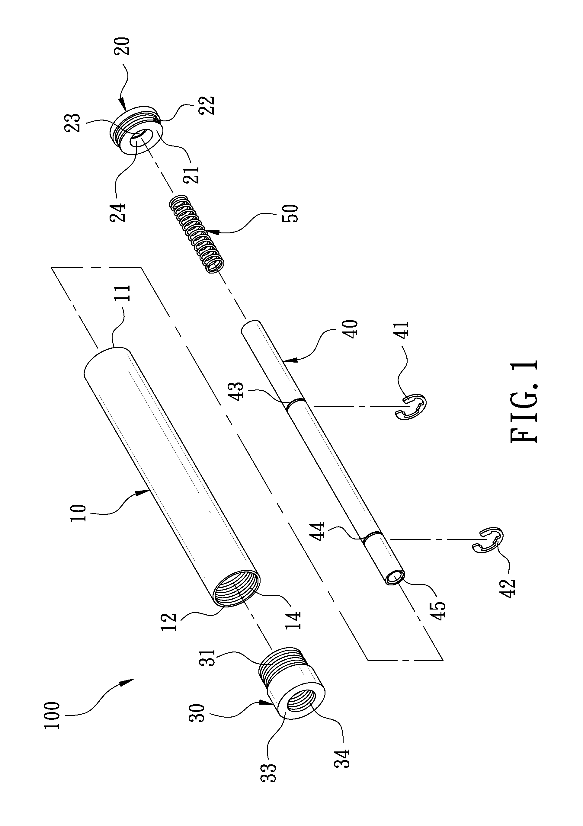
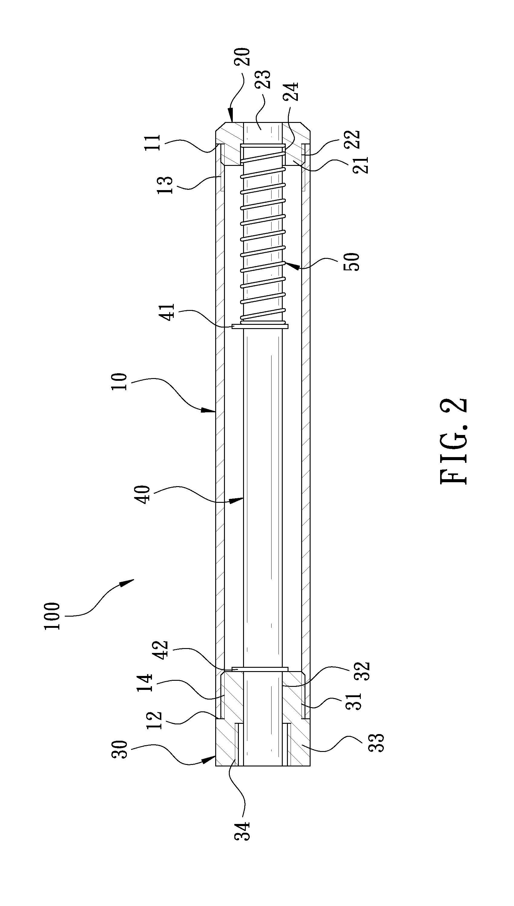
[0014]As shown in FIG. 1 and FIG. 2, an initial velocity accelerating tube 100 according to a preferred embodiment of the present invention comprises an outer pipe 10, a stop member 20, a connection member 30, an inner pipe 40, and an elastic member 50.

[0015]The outer pipe 10 has a length ranged from 15 to 30 centimeters. The outer pipe 10 has a first opening 11 and a second opening 12 at two ends thereof. An inner wall of the outer pipe 10 has first inner threads 13 close to the first opening 11 and second inner threads 14 close to the second opening 12.

[0016]The stop member 20 is disposed at the first opening 11 of the outer pipe 10. The stop member 20 may be integrally formed with the outer pipe 10. In this embodiment, the stop member 20 has a protruding portion 21 at one end thereof. The protruding portion 21 has a diameter smaller than that of th...


PUM


Abstract

An initial velocity accelerating tube includes an outer pipe. Two ends of the outer pipe are connected with a stop member and a connection member, respectively. An inner pipe is provided in the outer pipe. Two ends of the inner pipe are inserted in the stop member and the connection member, respectively. When the initial velocity accelerating tube is mounted on a toy gun, one end of the inner pipe is against the front end of the barrel of the toy gun by the elastic force of the elastic member so as to tightly connect the barrel, providing an airtight effect. The barrel can be lengthened. To have a shoot with the long-barreled gun, the bullet can have a longer route to accelerate for getting a higher initial velocity.

Description

BACKGROUND OF THE INVENTION[0001]1. Field of the Invention[0002]The present invention relates to an initial velocity accelerating tube for a toy gun.[0003]2. Description of the Prior Art[0004]A toy gun has a main body and a barrel in the main body. One end of the barrel has a muzzle, and the other end of the barrel is connected with a percussion mechanism. The percussion mechanism uses a cylinder to push air for firing bullets. The bullets move along the barrel for shooting. According to the physical law, the initial velocity of the bullet and the route are in a direct ratio. In other words, the higher the initial velocity is, the farther object will be shot. The initial velocity of the bullet depends on the length of the barrel. When the toy gun is fired, the gas will be ejected through the percussion mechanism until the bullet reaches the muzzle. That is to say, the longer the barrel is, the longer accelerating route will be got after firing the bullet for getting more kinetic ene...

Claims


Application Information

Patent Timeline
IPC IPC(8): F41B11/12
CPCF41A21/32F41B11/00F41A21/48F41B11/89
Inventor CHEN, JEFFREY
Owner J B UNICORN
Why Eureka
Try Eureka