Vortex ring exciter based on pressure loss control

An exciter and vortex ring technology, applied in the field of vortex ring exciters, can solve the problems of high impact and noise, the ventilation volume of the vortex ring cannot meet the requirements, and the performance of the motor cannot be maximized.

Active Publication Date: 2021-09-14
WUHAN UNIV OF TECH
View PDF7 Cites 2 Cited by
  • Summary
  • Abstract
  • Description
  • Claims
  • Application Information

AI Technical Summary

Problems solved by technology

[0002] In the existing vortex ring generating device, the vortex rings are mainly generated intermittently one by one, and the ventilation rate is greatly limited. For the heating or cooling fields with the minimum ventilation rate standard, the vortex ring ventilation rate produced by it cannot meet the requirements.
Moreover, the existing axial disturbance vortex ring device relies on the electromagnet to directly impact and disturb the film, the

Method used


Image

  • Vortex ring exciter based on pressure loss control
  • Vortex ring exciter based on pressure loss control
  • Vortex ring exciter based on pressure loss control

Examples


Embodiment Construction

[0027] The present invention will be described in detail below in conjunction with the accompanying drawings and embodiments.

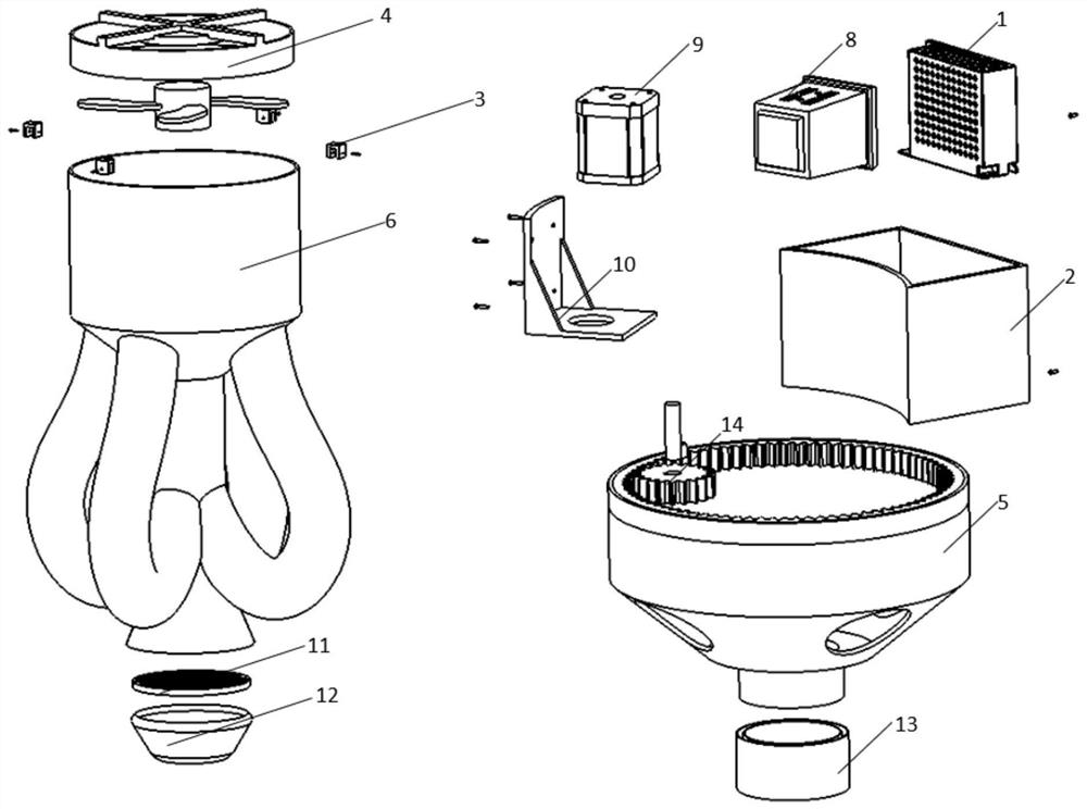
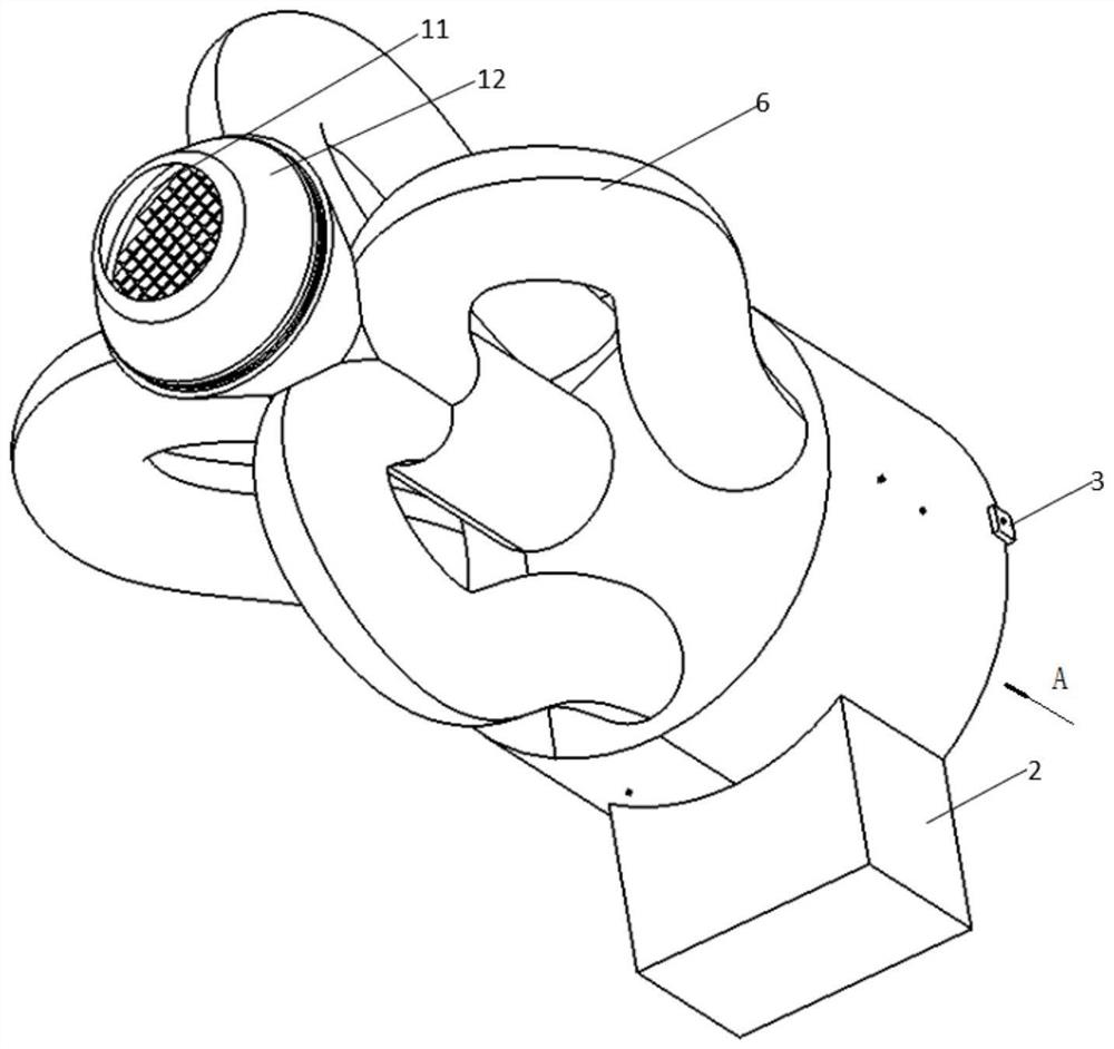
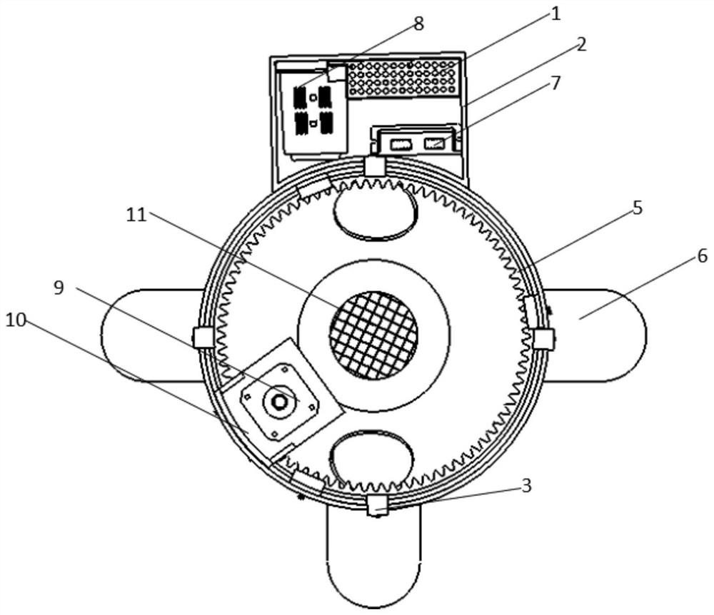
[0028] refer to Figure 1 to Figure 8 As shown, the vortex ring exciter based on pressure loss control in an embodiment provided by the present invention includes an axial flow fan 4, a main air supply duct 15, a interceptor, a tapering nozzle 12 and a plurality of hedging and intercepting ducts 6, and the shaft The flow fan 4 is arranged at the inlet end of the main air supply duct 15, the tapered nozzle 12 is arranged at the outlet end of the main air supply duct 15, and a plurality of hedging cut-off pipes 6 are evenly distributed along the circumference of the main air supply pipe 15, and the hedging cut-off pipes 6 The inlet of the inlet is communicated with the upper inner cavity of the main air supply duct 15, and the outlet of the hedging cut-off pipeline 6 is communicated with the lower inner cavity of the main air supply duct 15, and the cut...


PUM


Abstract

The invention discloses a vortex ring exciter based on pressure loss control. The vortex ring exciter comprises a fan, an air supply main pipeline, cut-off devices, a convergent nozzle and a plurality of opposite-impact cut-off pipelines, wherein the fan is arranged at the inlet end of the air supply main pipeline, the convergent nozzle is arranged at the outlet end of the air supply main pipeline, the plurality of opposite-impact cut-off pipelines are uniformly distributed in the circumferential direction of the air supply main pipeline, an inlet of each opposite-impact cut-off pipeline is in communication with an upper inner cavity of the air supply main pipeline, an outlet of each opposite-impact cut-off pipeline is in communication with a lower inner cavity of the air supply main pipeline, and the cut-off devices are arranged at the inlets of the opposite-impact cut-off pipelines. According to the vortex ring exciter based on pressure loss control, opposite-impact type cut-off of air flow is achieved, reverse air flow of an opposite-impact flow channel is used for replacing an original cut-off plate, and closing and opening of a main flow channel of the air supply main pipe are achieved; and the structure is simpler, the service life of equipment is prolonged, and the quality of produced vortex rings is improved.

Description

technical field [0001] The invention specifically relates to a vortex ring actuator based on pressure loss control. Background technique [0002] In the existing vortex ring generating device, the vortex rings are mainly generated intermittently one by one, and the ventilation rate is greatly limited. For the heating or cooling field with the minimum ventilation rate standard, the vortex ring ventilation rate produced by it cannot meet the requirements. Moreover, the existing axial disturbance vortex ring device relies on the electromagnet to directly impact and disturb the film, the stroke is limited, and the disturbance effect is not ideal. If the motor is used to drive the screw to impact and disturb the film, it is inconvenient to achieve short-term high-speed and intermittent disturbance, and the continuous change of the direction of the motor makes the performance of the motor unable to maximize. If it is a moving structure, the impact and noise to achieve the above r...

Claims


Application Information

Patent Timeline
IPC IPC(8): F15D1/02F15D1/00F15C3/00
CPCF15D1/02F15D1/025F15D1/009F15C3/00
Inventor 徐琳郑心怡张昊侯宝珅吴双黄鑫同钱蕾江南雨沈艺馨戴露王莹琪王杰
Owner WUHAN UNIV OF TECH
Why Eureka
Try Eureka