Multi-band Antenna of Compact Size

Active Publication Date: 2007-08-30
HTC CORP
View PDF11 Cites 7 Cited by
  • Summary
  • Abstract
  • Description
  • Claims
  • Application Information

AI Technical Summary

Benefits of technology

[0006]A multi-band antenna according to the present invention includes a coupling portion for feeding-in or feeding-out signals. A first radiation portion is coupled to one end of the coupling portion. The first radiation portion is bended at one or more bending points to form a plurality of sections with the plurality of sections distributed on two planes that are not parallel to each other. A second r

Problems solved by technology

Therefore the development of antennas has also become one of key issues for vendors in the technology field.
However, when using this type of antenna as a multi-band antenna, a planar radiation portion of the antenna requires a large planar area, and a distance between the radiation pla

Method used


Image

  • Multi-band Antenna of Compact Size
  • Multi-band Antenna of Compact Size
  • Multi-band Antenna of Compact Size

Examples


Embodiment Construction

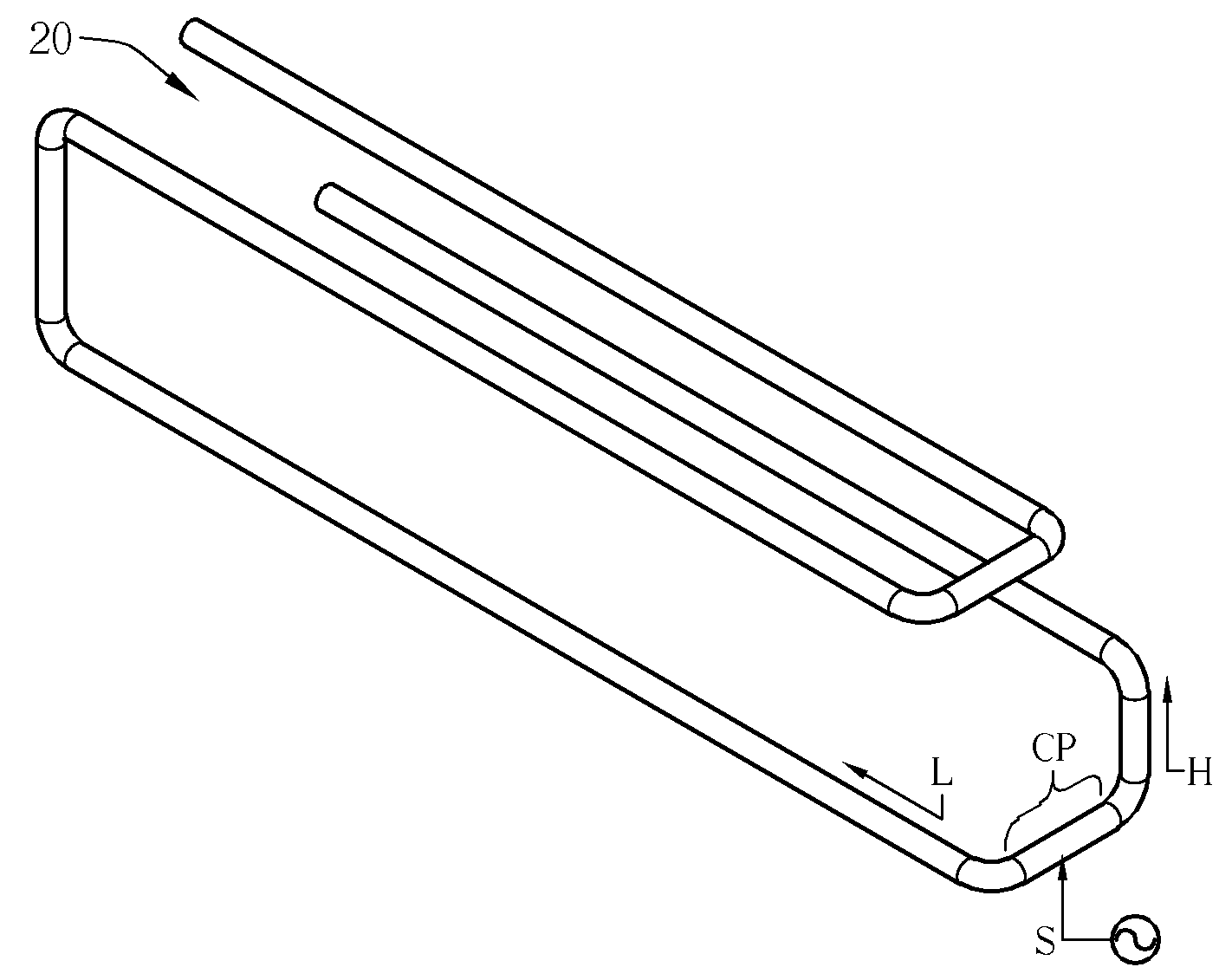
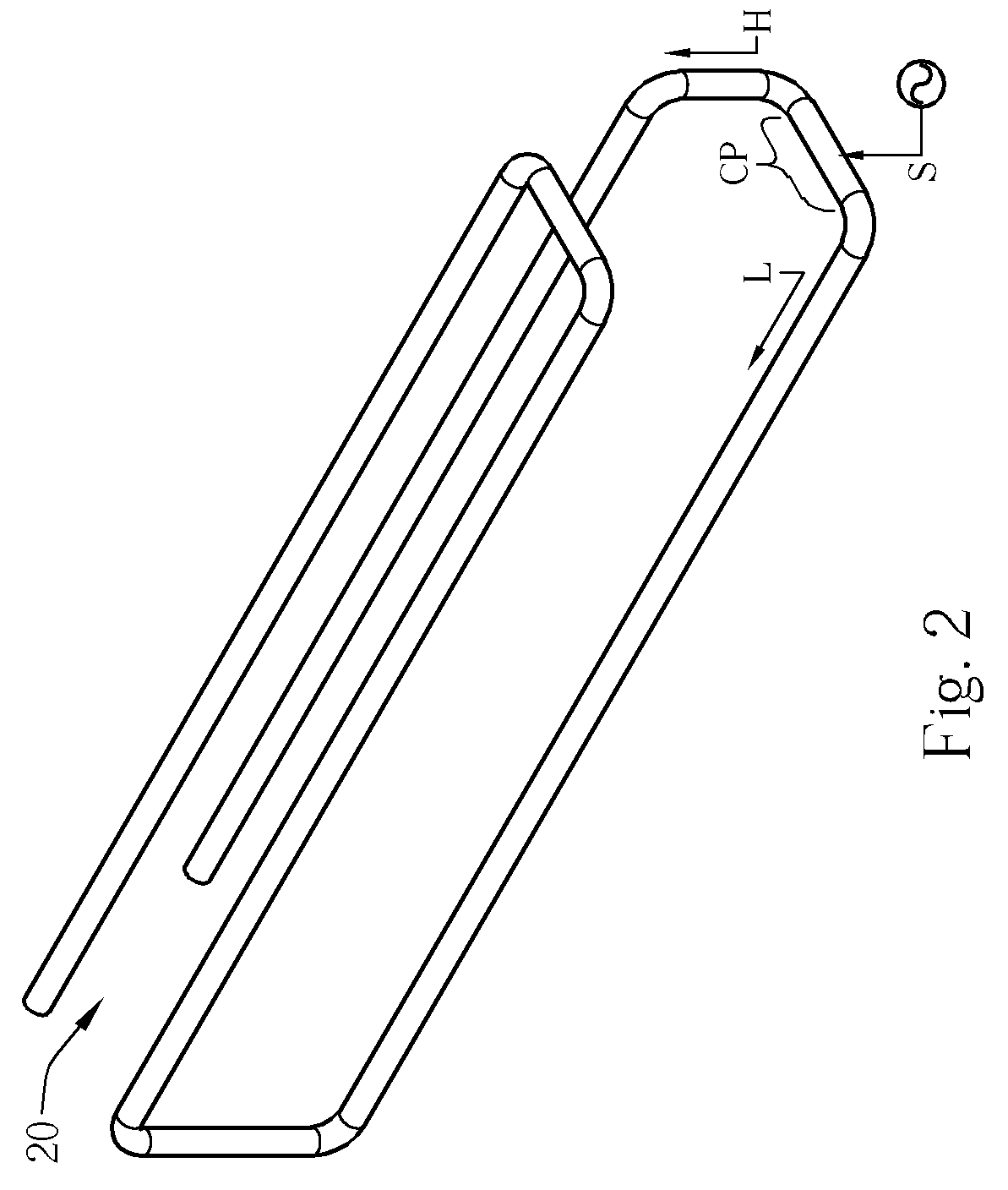
[0017]Please refer to FIGS. 2-5. FIGS. 2-5 are diagrams with different viewing angles of an embodiment 20 of an antenna of the present invention. The antenna of the present invention 20 can be a monopole antenna, with a coupling portion CP, a low frequency radiation portion L, and a high frequency radiation portion H to have the antenna of the present invention 20 functioning in multi-band and supporting different requirements from each frequency band of wireless communications. As shown in FIGS. 2-5, the antenna 20 can be formed with bended conductors having uniform cross sections (for example, a copper wire having circular cross sections). The low frequency radiation portion L and the high frequency radiation portion H are extensions of different (opposite) ends of the coupling portion CP and hence form a three-dimensional structure. The coupling portion CP feeds-in or feeds-out signals with a signal feeding point S, the low frequency radiation portion L and the high frequency rad...


PUM


Abstract

A multi-band antenna of compact size includes a conductor of uniform cross-section folded to form the antenna with a connection portion, a low-frequency first radiation portion, and a high-frequency second radiation portion. The connection portion has a feeding point for signal feeding. The first and second radiation portions connect to two ends of the connection portion. The first radiation portion is folded along two different planes to form three main sections. The second radiation portion is folded along a plane to form two sections. A terminal section of the first radiation portion and a terminal section of the second radiation portion are parallel, such that radiation of these two sections is coupled to enhance radiation characteristics of the antenna. Also, the folded structure helps to achieve compact size of the antenna.

Description

BACKGROUND OF THE INVENTION [0001]1. Field of the Invention[0002]The present invention provides a multi-band antenna of compact size, in particular a monopole antenna of a compact size with a three-dimensional bending structure that uses a characteristic of coupling effectively between different frequency bands to improve the antenna's efficiency.[0003]2. Description of the Prior Art[0004]In a modern world of information, various wireless communication networks have become one of the most important channels for exchanging sounds, text, numerical results, data, and video for many people. An antenna is required to receive information carried by wireless electromagnetic waves in a wireless communications network. Therefore the development of antennas has also become one of key issues for vendors in the technology field. In order to have users implement and access information from different wireless networks in ease, an antenna with better design should be able to cover different bands ...

Claims


Application Information

Patent Timeline
IPC IPC(8): H01Q1/24H01Q5/10
CPCH01Q9/28
Inventor CHEN, YUN-TACHOU, CHIEN-PANGHSIEH, CHANG-HAO
Owner HTC CORP
Why Eureka
Try Eureka