Driver for induction motor and method of driving the same

Active Publication Date: 2007-09-13
HITACHI IND EQUIP SYST CO LTD
View PDF11 Cites 10 Cited by
  • Summary
  • Abstract
  • Description
  • Claims
  • Application Information

AI Technical Summary

Benefits of technology

[0009]In the light of the foregoing, it is therefore an object of the present invention to provide a driver for an induction

Problems solved by technology

As a result, it is impossible to lift the load.
On the other hand, even when the acceleration a is positive, if a rate of change in speed expressed by dω*/dt is larger than the value (maximum value of torque τm−M·g·r)/J, the motor cannot follow a command, and thus the lifting fails.
Thus, there is the possibility that the magnitud

Method used


Image

  • Driver for induction motor and method of driving the same
  • Driver for induction motor and method of driving the same
  • Driver for induction motor and method of driving the same

Examples


embodiment 1

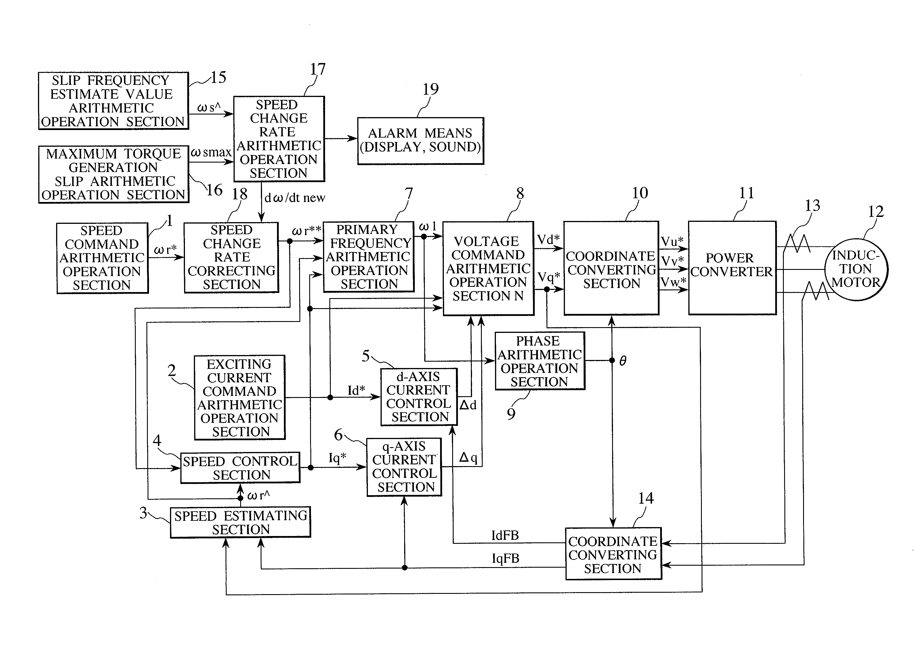
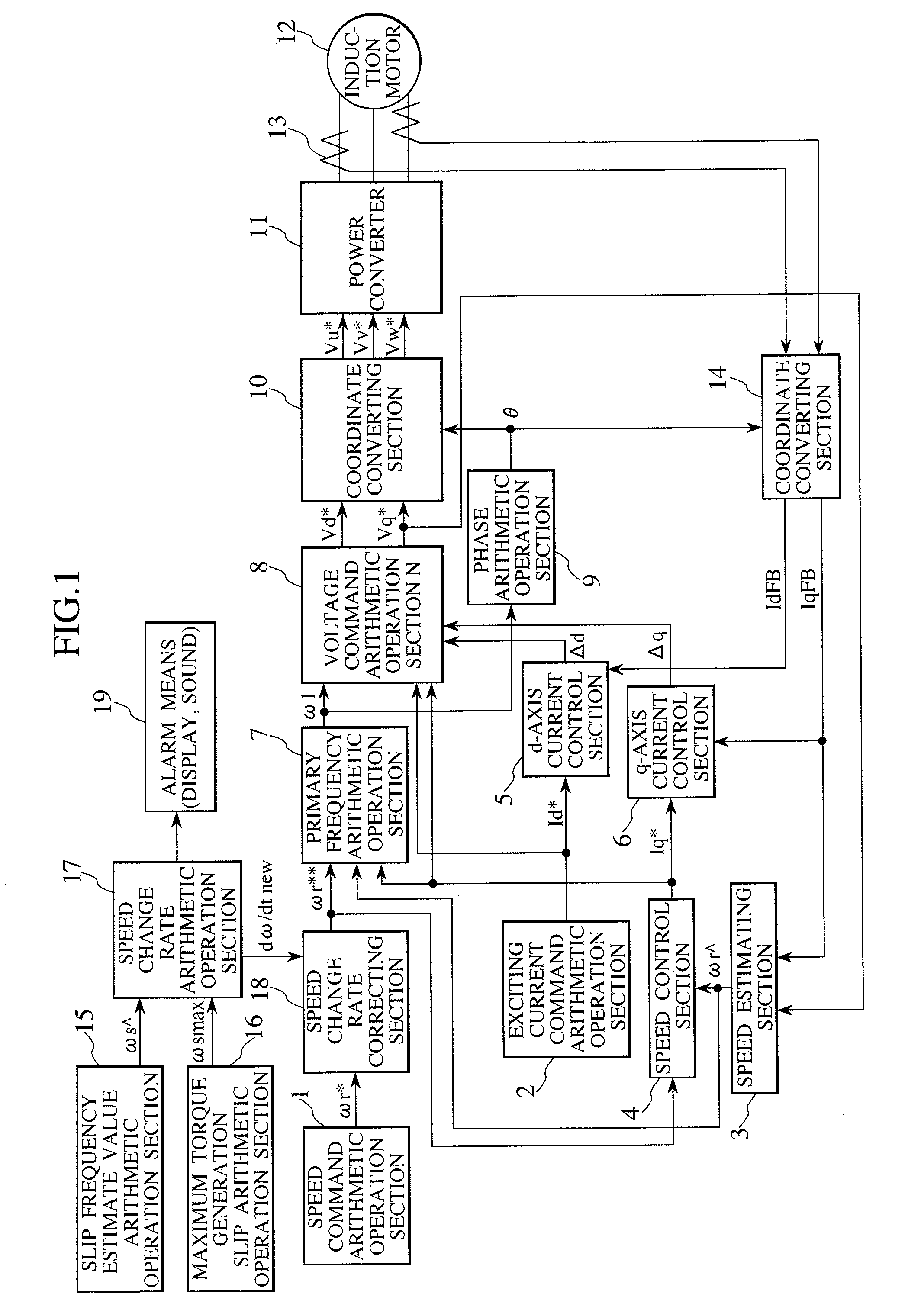
[0025]FIG. 1 is a block diagram showing overall control for a driver for an induction motor according to Embodiment 1 of the present invention. Firstly, a driving control system for an induction motor based on vector control will now be described.

[0026]A speed command arithmetic operation section 1 outputs a speed command ωr*. When an induction motor is accelerated, the speed command ωr* is changed with time at a predetermined rate of change. An exciting current command arithmetic operation section 2 arithmetically operates an exciting current command Id*. A speed estimating section 3 arithmetically operates a speed estimate value ωr̂ based on a current feedback value, a voltage command and the like. Note that, various kinds of methods are known as a method of arithmetically operating the speed estimate value ωr̂. The present invention can also be applied to another method of estimating the value ωr̂ other than the estimating method described in Embodiment 1. A speed control section...

embodiment 2

[0050]A description will now be made of a difference between a driver for an induction motor according to Embodiment 2 of the present invention and the driver of Embodiment 1. For example, there is considered the case where contrary to Embodiment 1, the exciting current Id is held substantially at zero, that is, at Id=0 in the lower speed range, and the q-axis current Iq corresponding to the rated current larger than the normal rated torque current is caused to flow in the induction motor 12. The slip frequency estimate value ωŝ is expressed in the form of a stationary solution obtained by setting Id=0 in Expression (8) by Expression (20). For example, Φ2d̂ and Φ2q̂ expressed by Expressions (6) and (7) may be used as Φ2d and Φ2q, respectively.

ωŝ=1 / Ts·Φ2d / Φ2q   (20)

[0051]Suffixes d and q are replaced with each other and a polarity sign is inversed in Expression (10) in Embodiment 1, thereby obtaining the slip frequency ωŝ of Expression (20). Therefore, expressions of the generated...

embodiment 3

[0052]A description will now be made of a difference between a driver for an induction motor according to Embodiment 3 of the present invention and the driver of Embodiment 1. In Embodiment 3, zero is given as dω / dt2 in the optimal speed change rate arithmetic operation section 173 shown in FIG. 4. As a result, when the rate of change in the speed command ωr* is too large as compared with the load and the slip frequency ωŝ exceeds the threshold ωsmaxTH in the speed change rate setting section 174, the speed change rate setting section 174 outputs zero as dω / dtnew, and the slip frequency command ωr* is fixed in the speed change rate correcting section 18. After that, when the slip frequency ωŝ decreases to a level equal to or lower than the threshold ωsmaxTH, the speed change rate correcting section 18 does not correct the rate of change in the slip frequency command ωr* since the speed change rate setting section 174 outputs the initialized rate of change in the speed. In Embodime...


PUM


Abstract

An object of the present invention is to provide a driver for an induction motor which performs an operation at an acceleration suitable for the magnitude of a load and is excellent in efficiency, without an acceleration failure.
The driver for an induction motor includes a slip frequency estimate value arithmetic operation section 15 for arithmetically operating a slip frequency ωŝ of an induction motor 12, and a maximum torque generation slip arithmetic operation section 16 for arithmetically operating a slip frequency ωsmax at which a maximum torque is generated. When the slip frequency ωŝ exceeds a predetermined value ωsmaxTH(=0.96ωsmax, etc.) corresponding to the slip frequency ωsmax at which the maximum torque is generated, a speed change rate arithmetic operation section 17 and a speed change rate correcting section 18 reduce a rate of increase in a speed command ωr*.
In addition, when the slip frequency approaches the maximum torque generation slip frequency too closely, the load concerned is judged to be overloaded, and an alarm is generated.

Description

BACKGROUND OF THE INVENTION[0001]1. Field of the Invention[0002]The present invention relates to a driver for an induction motor which drives the induction motor in a variable speed manner, and a method of driving an induction motor, and more particularly to a driver for an induction motor which is suitable for the case where a crane apparatus or the like with which loads are lifted is driven, and a method of driving an induction motor.[0003]2. Description of the Related Art[0004]When loads are lifted at an acceleration α with a lifting and lowering apparatus such as a crane, as shown in Expression (1), a necessary torque τm depends on the acceleration α, and a weight m·g of a load. Note that, it is assumed in Expression (1) that a load is lifted with a pulley having a radius r.M·α·r=J·dω / dt=τm−m·g·r   (1)where J is a total inertia moment in a system including a motor and a mechanical system (having the pulley and the like), ω is a rotational speed of the motor, m is a mass of the l...

Claims


Application Information

Patent Timeline
IPC IPC(8): H02P27/04H02P21/00H02P21/14H02P21/18H02P21/22H02P21/24H02P23/08H02P23/14H02P23/16H02P27/06
CPCH02P21/085H02P29/028H02P23/0063H02P21/09H02P23/20H02P29/032
Inventor NAGATA, KOICHIROOKUYAMA, TOSHIAKIYAMAMOTO, KOUKITOMITA, HIROYUKI
Owner HITACHI IND EQUIP SYST CO LTD
Why Eureka
Try Eureka