Lighting device

Active Publication Date: 2007-10-11
CREELED INC
View PDF20 Cites 275 Cited by
  • Summary
  • Abstract
  • Description
  • Claims
  • Application Information

AI Technical Summary

Benefits of technology

[0031] In accordance with one aspect of the present invention, by spatially separating the solid state light emitter from the luminescent element, this extraction efficiency can be improved. In addition, by making the surface area of the illumination surface of the solid state light emitter which face

Problems solved by technology

Back scattered light which is scattered back into the light emitting diode chip itself has a very low pr

Method used


Image

  • Lighting device
  • Lighting device
  • Lighting device

Examples


Embodiment Construction

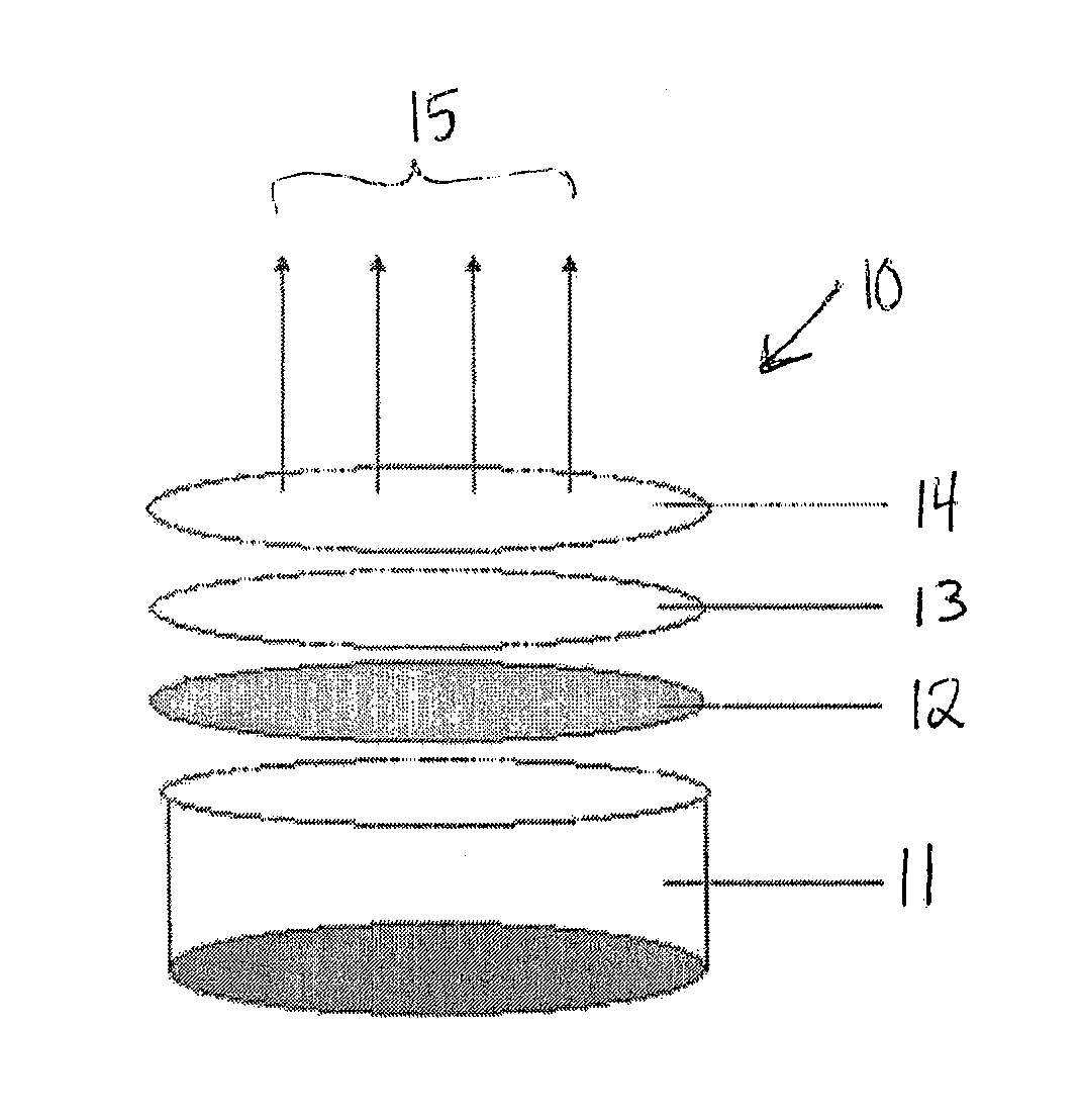
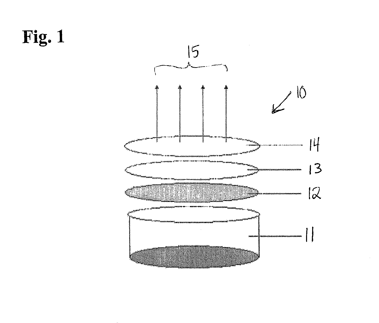
[0052] As noted above, in accordance with various aspects of the present invention, there is provided a lighting device comprising at least one solid state light emitter and at least one luminescent element, the luminescent element comprising at least one luminescent material.

[0053] Any desired solid state light emitter or emitters can be employed in accordance with the present invention. Persons of skill in the art are aware of, and have ready access to, a wide variety of such emitters. Such solid state light emitters include inorganic and organic light emitters. Examples of types of such light emitters include light emitting diodes (inorganic or organic), laser diodes and thin film electroluminescent devices, a variety of each of which are well-known in the art. As noted above, a wide variety of luminescent materials (also known as lumiphors or luminophoric media, e.g., as disclosed in U.S. Pat. No. 6,600,175, the entirety of which is hereby incorporated by reference) are well-kn...


PUM


Abstract

A lighting device comprising at least one solid state light emitter and at least one luminescent element spaced from the light emitter, a surface of the luminescent element being at least twice as large as the illumination surface of the light emitter. Also, a lighting device comprising at least one solid state light emitter and at least one luminescent element spaced from the light emitter, a surface of the luminescent element surface being at least twice as large as and substantially parallel to the illumination surface of the light emitter. Also, a lighting device comprising at least one solid state light emitter and at least one luminescent element spaced from the light emitter, a surface area of a projection of the luminescent element being at least twice as large as a surface area of a projection of the light emitter.

Description

CROSS-REFERENCE TO RELATED APPLICATIONS [0001] This application claims the benefit of U.S. Provisional Patent Application No. 60 / 753,138, filed Dec. 22, 2005, the entirety of which is incorporated herein by reference. [0002] This application claims the benefit of U.S. Provisional Patent Application No. 60 / 831,775, filed Jul. 19, 2006, the entirety of which is incorporated herein by reference.FIELD OF THE INVENTION [0003] The present invention relates to a lighting device, in particular, a device which includes one or more solid state light emitters and one or more luminescent materials (e.g., one or more phosphors). In a particular aspect, the present invention relates to a lighting device which includes one or more light emitting diodes, and one or more luminescent materials. BACKGROUND OF THE INVENTION [0004] A large proportion (some estimates are as high as one third) of the electricity generated in the United States each year goes to lighting. Accordingly, there is an ongoing ne...

Claims


Application Information

Patent Timeline
IPC IPC(8): F21V9/16H01L33/50
CPCH01L33/505F21K9/00F21K9/56F21V9/16H01L2924/0002F21Y2101/02H01L2924/00F21V29/67F21K9/64F21Y2115/10F21V9/30H01L33/507F21V13/14
Inventor NEGLEY, GERALD H.
Owner CREELED INC
Why Eureka
Try Eureka