Flexible annuloplasty prosthesis and holder

a flexible annuloplasty and prosthesis technology, applied in the field of surgical tools, can solve the problems of not being able to easily deflect outward to allow outward movement, and achieve the effect of facilitating the removal of the holder

Inactive Publication Date: 2007-11-01
MEDTRONIC INC
View PDF99 Cites 124 Cited by
  • Summary
  • Abstract
  • Description
  • Claims
  • Application Information

AI Technical Summary

Benefits of technology

[0010] The present invention generally is intended to provide a simplified and more easily employed mechanism for holding the annuloplasty prosthesis during passage of the sutures through the prosthesis and for releasing it from the holder after the ring has been moved downward into its intended location on the valves annulus.
[0012] The suture guide may be any elongated structure, such a rod, bar or cord, but in the preferred embodiment of the invention, the suture guide takes the form of a suture or sutures, extending across the opening through the holder. Cutting the suture allows it to be pulled through the knots at the leaflet edge, facilitating removal of the holder. In the disclosed embodiment, the suture or sutures extending across the central opening are extensions of sutures holding the first and second components closely adjacent one another, routed so that cutting the sutures to allow their removal from the knots at the leaflet edge also releases the first and second components so that the second component may move upward relative to the first component, allowing removal of the annuloplasty prosthesis from the holder.

Problems solved by technology

These penetrating members may be fabricated of metal or molded plastic and are sufficiently rigid that they are not readily deflected outward to allow outward movement of the annuloplasty prosthesis away from the holder.

Method used


Image

  • Flexible annuloplasty prosthesis and holder
  • Flexible annuloplasty prosthesis and holder
  • Flexible annuloplasty prosthesis and holder

Examples


Embodiment Construction

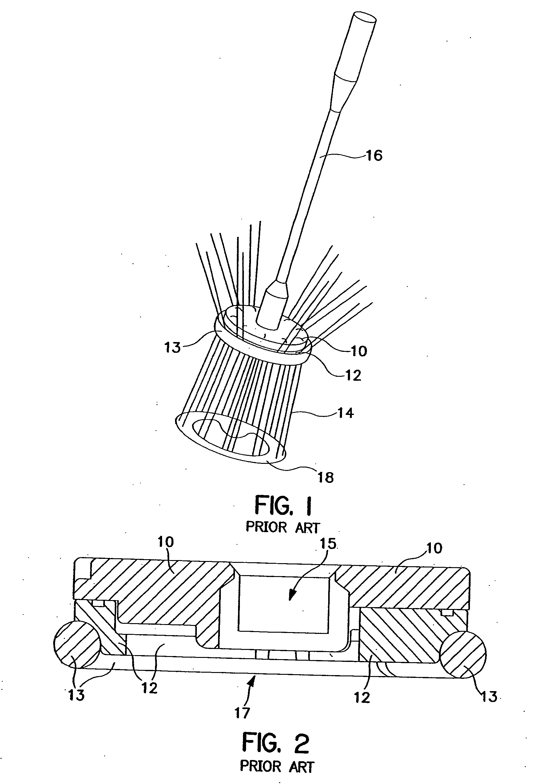
[0025]FIG. 1 is a perspective view of a two-piece annuloplasty holder according to the prior art. In particular, the holder system as illustrated is described in the brochure “Medtronic Duran Flexible Annuloplasty Systems In Service Guide”, published by Medtronic, Inc. in 2000, Publication No. UC200004685 EN, incorporated herein by reference in its entirety. The holder system includes a handle 16 which may be made of metal or plastic, and which may, in some embodiments, include a malleable shaft allowing for manual reconfiguration of the shaft. The shaft is snapped into the holder itself, which includes two components 10 and 12 that are molded of rigid plastic. The upper component 10 of the holder is transparent and serves as a template, including markings illustrating the locations of the valve trigones and regularly spaced markings assisting in placement of sutures around the annuloplasty prosthesis 13. As illustrated, the first component 12 of the prosthesis releasably secured to...


PUM


Abstract

A valve repair system, preferably including an annuloplasty prosthesis and a holder for the prosthesis. The holder includes a first component having a central opening, a circumferential surface and an outwardly extending member. The annuloplasty prosthesis is located adjacent to the circumferential surface, above the outwardly extending member. The holder further includes a second component movable upwardly relative to the first holder component and includes a rigid penetrating member extending downward from the second component into the prosthesis, holding it adjacent the circumferential surface. The holder also includes a suturing guide for assisting a physician in valve repair surgery, which may be a cuttable suture extending across the central opening along a path approximating a desired line of leaflet coaption. The cuttable suture may additionally secure the first and second components to one another. The suturing guide may also be incorporated into one-piece annuloplasty prosthesis holders or into stand-alone tools that do not carry annuloplasty prostheses.

Description

CROSS-REFERENCE TO RELATED APPLICATIONS [0001] This application is a divisional of U.S. patent application Ser. No. 10 / 174,199, filed Jun. 19, 2002, which was a continuation-in-part of U.S. patent application Ser. No. 10 / 100,444, filed Mar. 18, 2002, now U.S. Pat. No. 6,719,786.BACKGROUND OF THE INVENTION [0002] The present invention relates generally to surgical tools and more particularly for surgical tools used in conjunction with valve repair, including tools for holding prostheses such as annuloplasty rings and bands. [0003] Annuloplasty rings and bands are useful in a variety of surgical procedures, including mitral and tricuspid annular reduction. In these procedures, sutures are first placed around all or portions of the valve annulus at spaced intervals. Sutures passing through the annulus in regions in which reduction of the valve annulus is desired are spaced equidistant from one another, for example, at 4 mm intervals. These sutures are then brought through the annulopla...

Claims


Application Information

Patent Timeline
Patent Type & Authority Applications(United States)
IPC IPC(8): A61F2/06A61F2/24A61B17/04A61B17/00
CPCA61B17/0467A61B2017/00243A61F2/2409Y10S623/904A61F2/2448A61F2/2466A61F2/2427
Inventor RYAN, TIMOTHY R.MORROW, JOSEPH C.DURAN, CARLOS G.
Owner MEDTRONIC INC
Why Eureka
Try Eureka