Annuloplasty system
a technology of annuloplasty and a stent, applied in the field of surgical tools, can solve the problems of not being able to easily deflect outward to allow outward movement, and achieve the effect of convenient use and simplified
- Summary
- Abstract
- Description
- Claims
- Application Information
AI Technical Summary
Benefits of technology
Problems solved by technology
Method used
Image
Examples
first embodiment
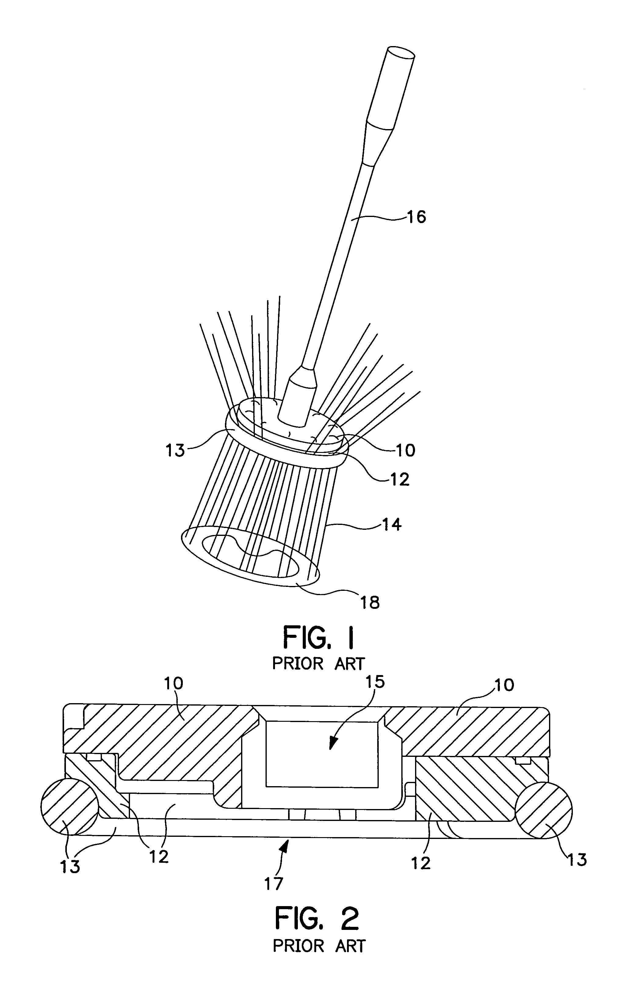
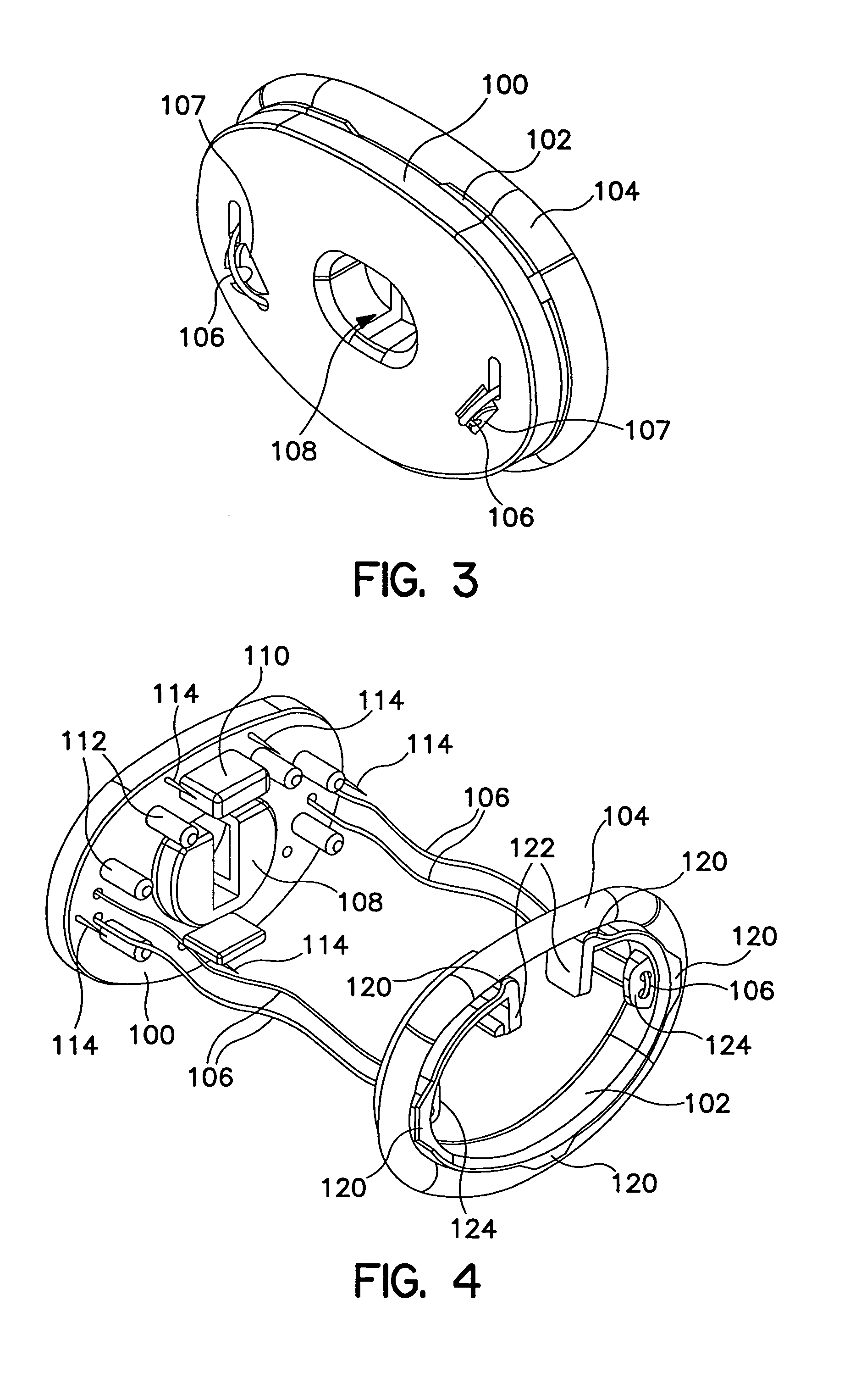
[0042]FIG. 3 is a perspective view from the upper surface of a two-component annuloplasty valve holder according to the present invention. The holder includes a first component 102, around which the annuloplasty prosthesis 104 is mounted and a second component 100, releasably secured to the first component by means of sutures 106. Sutures 106 pass through both the first and second components of the holder and, upon cutting at slots 107, release the first and second components from one another. The second component also includes a formed recess 108 corresponding to that illustrated in FIG. 2, for releasably receiving a handle, which may correspond to handle 16, illustrated in FIG. 1. As is the case for the alternative embodiments discussed below, recess 108 may be replaced by a snap fitting, a threaded bore, or other mechanism for connecting to a handle.
[0043]FIG. 4 illustrates the components of the holder of FIG. 3 spaced from one another, as seen from below the two components. In t...
second embodiment
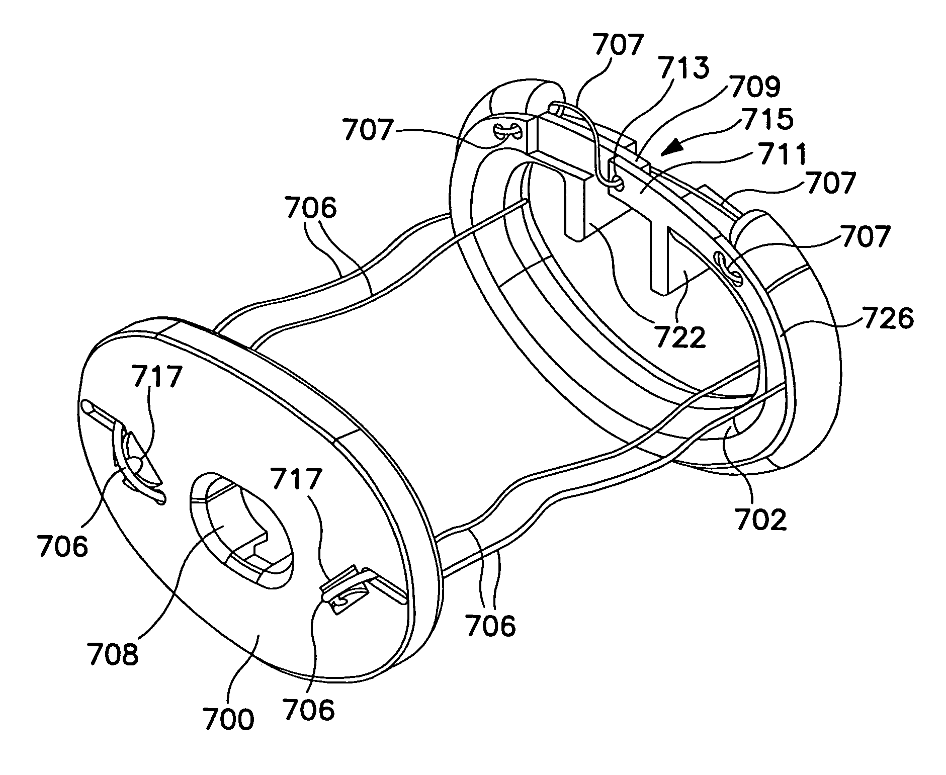
[0052]FIG. 7 is a perspective view of a two-piece holder according to the present invention, with handle 209 attached. In this embodiment, annuloplasty prosthesis 204 is mounted against an outer circumferential surface of first holder component 202, which is in turn retained against second holder component 200. The second holder component 20 is provided with a snap fitting 210, engaging a pin on the end of the handle 209. The snap fitting may be replaced by a threaded recess or other mechanical mechanism for connecting to the handle 209. Snap fitting 210 is mounted to a removable base 211, which is retained to cross bar 208 of component 200 by means of suture 213, which is captured to base 211. Handle 209 and base 211 are removed together after cutting suture 213 at slot 215. Sutures 206 retain component 200 adjacent component 202. Sutures 206 are tied to component 200 in the vicinity of grooves 207 and 205. When cut at grooves 207, component 200 is released to move upward relative ...
third embodiment
[0065]FIG. 13 is a perspective view of a two-component annuloplasty prosthesis holder according to the present invention. The holder of FIG. 13 operates in a fashion similar to the operation of the holders discussed above, maintaining the annuloplasty prosthesis 304 adjacent the outer circumferential surface of the first holder component 302 by means of barbs extending downwardly from second holder component 300 and into prosthesis 304. The first and second holder components 302 and 300 are retained adjacent to one another by means of a suture (not illustrated in this view) passing through aperture 306 in tab 301, extending upward from the first holder component 302. The prosthesis 304 is prevented from moving downwardly off of the barbs extending downward from second holder component 300 by means of circumferential ridge 320, extending radially outward from the first holder component 302, adjacent the lower surface of prosthesis 304. The interrelation of the various components is i...
PUM
 Abstract
Description
Claims
Application Information
 - R&D
- Intellectual Property
- Life Sciences
- Materials
- Tech Scout
- Unparalleled Data Quality
- Higher Quality Content
- 60% Fewer Hallucinations
Browse by: Latest US Patents, China's latest patents, Technical Efficacy Thesaurus, Application Domain, Technology Topic, Popular Technical Reports.
© 2025 PatSnap. All rights reserved.Legal|Privacy policy|Modern Slavery Act Transparency Statement|Sitemap|About US| Contact US: help@patsnap.com


