Air conditioner

a technology for air conditioners and fans, applied in the direction of motor/generator/converter stoppers, dynamo-electric converter control, multiple dynamo-motor starters, etc., can solve the problems of difficult to make the system inexpensive, conventional techniques, etc., and achieve the effect of increasing the starting torque and facilitating the system construction

Inactive Publication Date: 2007-12-13
PANASONIC CORP
View PDF4 Cites 27 Cited by
  • Summary
  • Abstract
  • Description
  • Claims
  • Application Information

AI Technical Summary

Benefits of technology

[0010]In the air conditioner according to the present invention having two compressors, when a first compressor is started, the phase advance capacitor for a second compressor is temporarily connected in parallel with the phase advance capacitor for the first compressor. And, when the second compressor is started, the phase advance capacit...

Problems solved by technology

The conventional technique, however, has the following problems.
The provi...

Method used


Image

  • Air conditioner
  • Air conditioner
  • Air conditioner

Examples


first embodiment

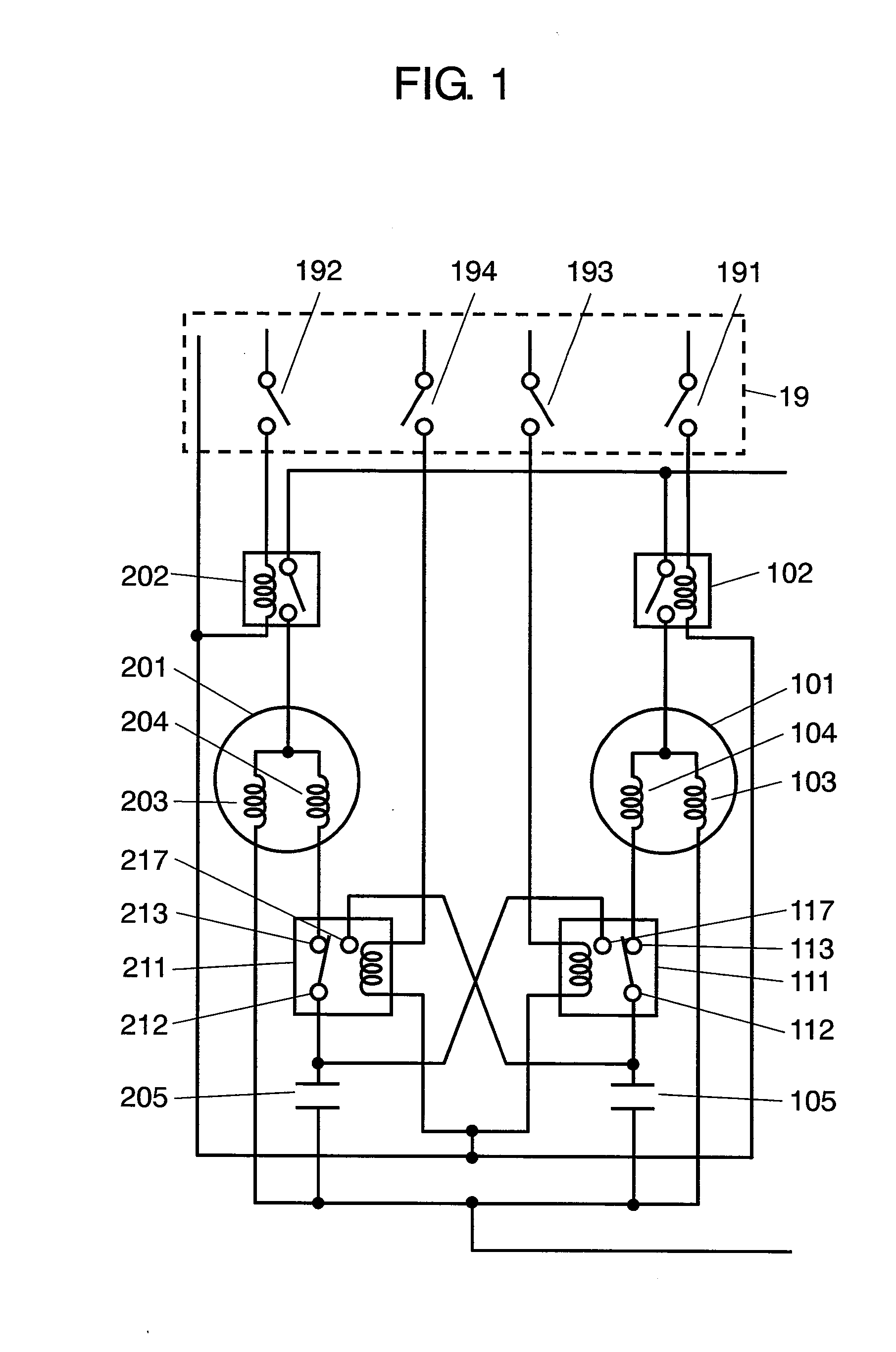
[0017]FIG. 1 is an electrical circuit diagram of an air conditioner according to a first embodiment of the present invention. The air conditioner includes two compressors: first compressor 101 and second compressor 201.

[0018]With reference to FIG. 1, the structure of the air conditioner according to the first embodiment of the present invention is described as follows.

[0019]Between auxiliary coil 104 of first compressor 101 and phase advance capacitor 105 (first phase advance capacitor) is provided switching relay 111 (first switching relay) which switches between two contacts. Common terminal 112 of switching relay 111 is connected to phase advance capacitor 105 for first compressor 101. Terminal 113, which is closed when the relay coil is not supplied with current, is connected to auxiliary coil 104 of first compressor 101. Terminal 117, which is closed when the relay coil is supplied with current, is connected to the wiring that connects auxiliary coil 204 of second compressor 20...

second embodiment

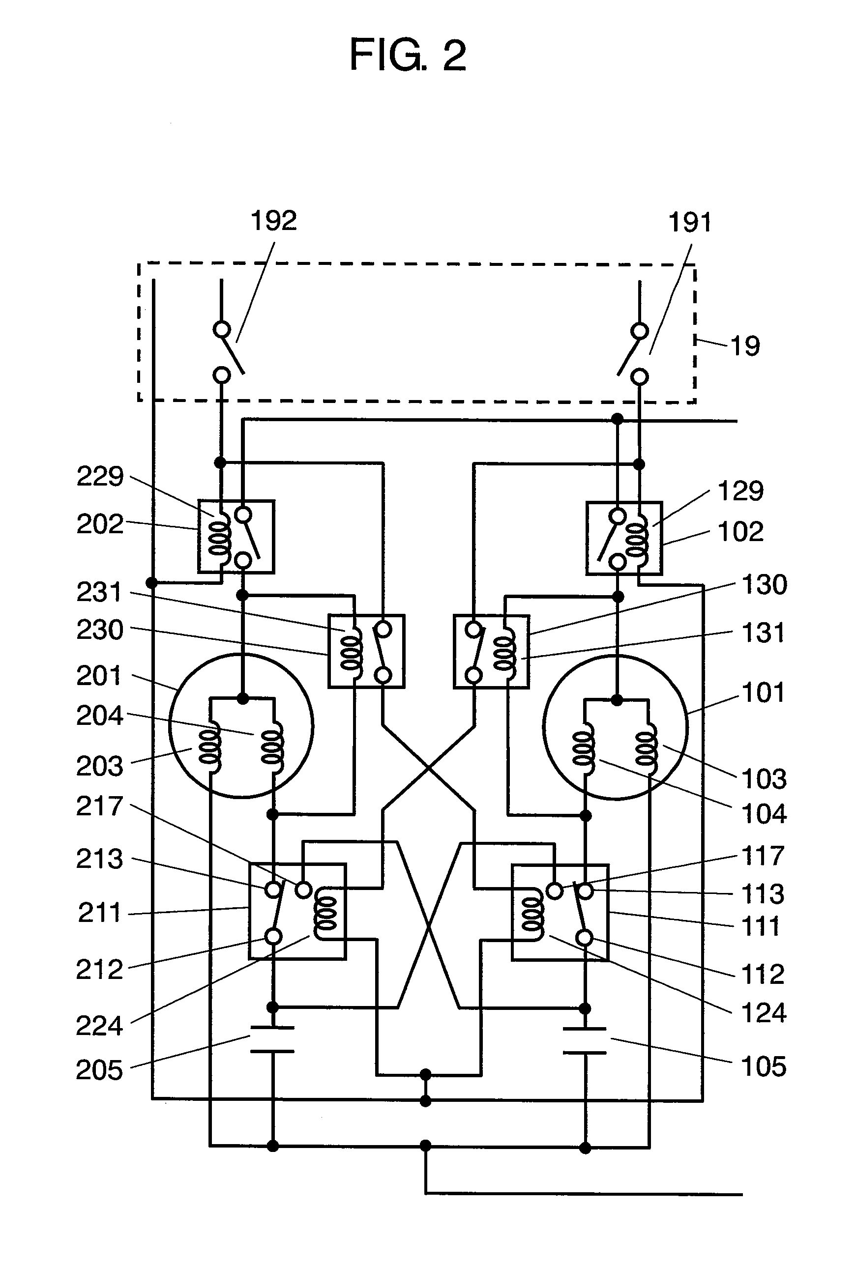
[0034]FIG. 2 is an electrical circuit diagram of an air conditioner according to a second embodiment of the present invention. The air conditioner includes two compressors: first compressor 101 and second compressor 201. The same components as those in the first embodiment are referred to with the same numerals and symbols as those in the first embodiment and may not described in detail again.

[0035]With reference to FIG. 2, the structure of the air conditioner according to the second embodiment of the present invention is described as follows.

[0036]Between auxiliary coil 104 of first compressor 101 and phase advance capacitor 105 (first phase advance capacitor) is provided switching relay 111 (first switching relay) which switches between two contacts. Common terminal 112 of switching relay 111 is connected to phase advance capacitor 105 for first compressor 101. Terminal 113, which is closed when the relay coil is not supplied with current, is connected to auxiliary coil 104 of fir...


PUM


Abstract

An air conditioner having two compressors enables, when one compressor is started, the phase advance capacitor for the other compressor to be temporarily separated and used in parallel with the phase advance capacitor for the one compressor. These compressors can have an increased starting torque without using a starting capacitor. This structure allows the effective use of expensive capacitors, making the system inexpensive.

Description

BACKGROUND OF THE INVENTION[0001]1. Field of the Invention[0002]The present invention relates to an air conditioner having two compressors.[0003]2. Background Art[0004]Conventionally, in an air conditioner having two compressors, each compressor has a phase advance capacitor and a starting capacitor, which increases the starting torque to start the compressor. After a compressor is started, the starting capacitor is separated from the circuit by a relay which detects the auxiliary coil current drawn by the compressor motor. One such conventional air conditioner is disclosed in Japanese Patent Unexamined Publication No. H10-019397.[0005]The conventional technique, however, has the following problems.[0006]FIG. 4 is an electrical circuit diagram of a conventional air conditioner. Of two compressors, first compressor 1 includes main coil 2 and auxiliary coil 3. Auxiliary coil 3 is connected to phase advance capacitor 4, and phase advance capacitor 4 is connected in parallel with starti...

Claims


Application Information

Patent Timeline
IPC IPC(8): F25B49/02
CPCF25B49/022F25B2500/26F25B2400/075
Inventor HATANO, KOJIKANZAKI, HIDEYUKIYAMADA, YOSHIHITO
Owner PANASONIC CORP
Why Eureka
Try Eureka