

Display apparatus and method for driving the same, and display driver and method for driving the same
- Summary
- Abstract
- Description
- Claims
- Application Information
AI Technical Summary
Benefits of technology
Problems solved by technology
Method used
Image

Examples
Embodiment Construction
[0048]A display driver and method for driving the same, and, a display apparatus and method for driving the same will be described in detail below through an embodiment thereof.
[0049]
[0050]First, a main configuration of a display pixel applied to a display apparatus according to the present invention and its control operation will be described with reference to the accompanying drawings.
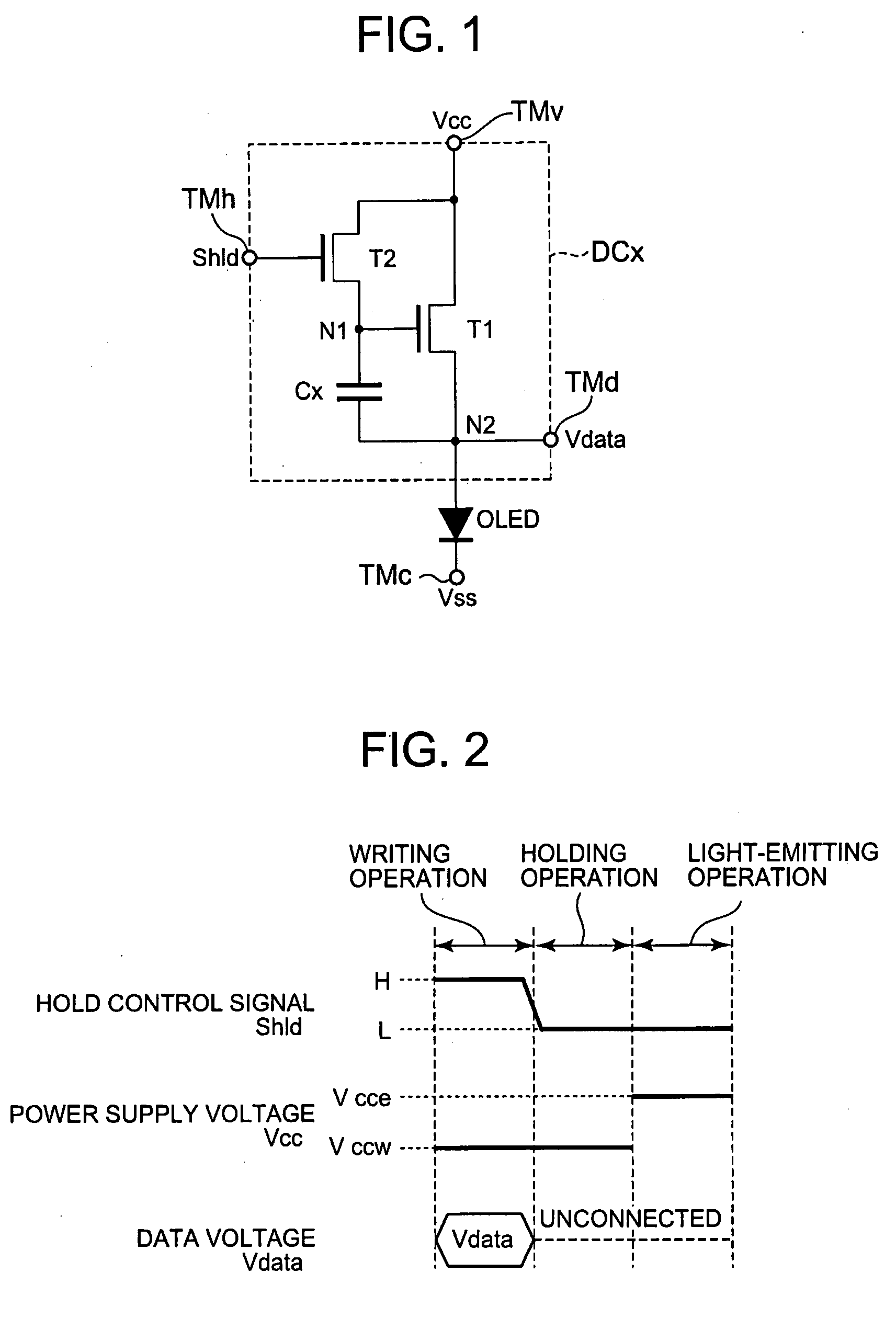
[0051]FIG. 1 is an equivalent circuit diagram showing a configuration of the main part of a display pixel which is applied to a display apparatus according to the present invention. In this example, an organic EL device is used as a current-drive type light-emitting device to be provided in a display pixel for descriptive purposes.
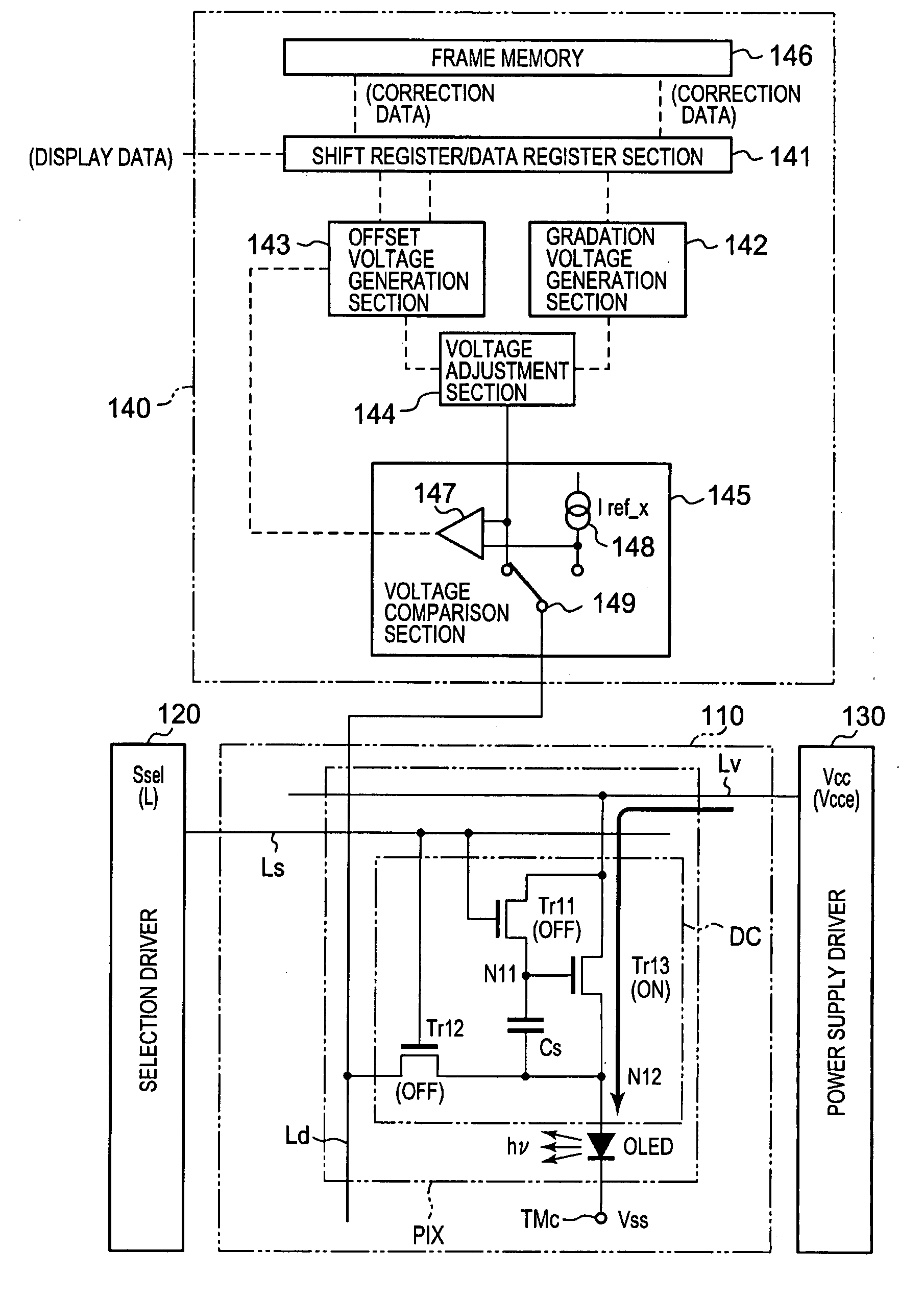
[0052]As shown in FIG. 1, a display pixel applied to a display apparatus according to the present invention has a circuit configuration including a pixel circuit section (corresponding to a pixel drive circuit DC to be described later) DCx and an organic EL device OLED whic...
PUM
 Abstract
Description
Claims
Application Information