Image coding apparatus, image coding method, image decoding apparatus, image decoding method and communication apparatus

a technology of image coding and image coding, applied in the direction of code conversion, color television with bandwidth reduction, television system, etc., can solve the problem of increasing the memory bandwidth needed for generating a predicted image, and achieve the effect of reducing memory bandwidth, improving coding efficiency, and improving memory bandwidth

Inactive Publication Date: 2008-03-13
MITSUBISHI ELECTRIC CORP
View PDF13 Cites 21 Cited by
  • Summary
  • Abstract
  • Description
  • Claims
  • Application Information

AI Technical Summary

Benefits of technology

[0019] As a result, the image coding apparatus in accordance with the present invention can perform compressing and coding on each frame of the input moving image signal with an improved degree of coding efficiency while reducing the memory bandwidth.
[0020] Furthermore, because the image coding apparatus can change the accuracy of motion compensated prediction according to the size of each region that is a unit for motion compensated prediction, and can also change the method of predictively coding motion vectors adaptively according to the size of each region that is a unit for motion compensated prediction, the image coding apparatus can assign a large amount of codes, which is increased as the coding efficiency is improved, to the motion vector while reducing the memory bandwidth. Therefore, the coding efficiency can be improved while the memory bandwidth is reduced.
[0029] As a result, the image decoding apparatus in accordance with the present invention can decode coded bitstreams on which compressing and coding is performed with an improved degree of coding efficiency and with the memory bandwidth being reduced.
[0030] Particularly, when a player for mainly playing back video images, the player including the image coding apparatus and the image decoding apparatus in accordance with the present invention, is incorporated into a piece of hardware such as a mobile phone or mobile information terminal equipment, a reduction in the memory bandwidth offers a remarkable advantage of simplifying the implementation of image decoding and reducing the electric power consumption of the hardware. While the cost of mounting those image coding and decoding apparatus into a piece of hardware, such as a mobile phone or mobile information terminal equipment, can be reduced, the transmission and recording efficiency of the hardware can be improved.

Problems solved by technology

However, a problem is that when calculating virtual samples at the boundaries a target block for prediction, because data about extra pixels that are placed outside of the target block, the number of pixels depending on the number of filter taps, are needed for filtering calculations, the memory bandwidth necessary for generation of a predicted image is increased according to the number of filter taps.

Method used


Image

  • Image coding apparatus, image coding method, image decoding apparatus, image decoding method and communication apparatus
  • Image coding apparatus, image coding method, image decoding apparatus, image decoding method and communication apparatus
  • Image coding apparatus, image coding method, image decoding apparatus, image decoding method and communication apparatus

Examples


embodiment 1

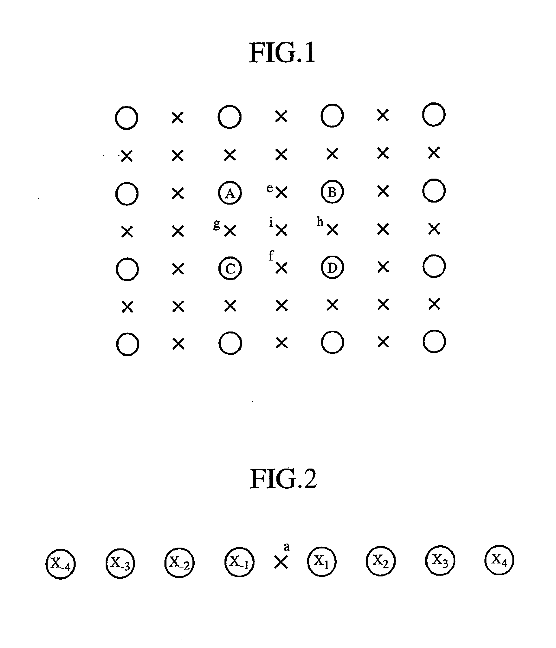
[0050] In this embodiment 1, an image coding apparatus and an image decoding apparatus each of which has a motion compensated prediction means capable of dividing each of a plurality of frames of a moving image into a plurality of macroblocks and further dividing each macroblock into a plurality of subblocks, and individually performing a motion compensated prediction on each of the plurality of subblocks will be explained. The features of the image coding apparatus and the image decoding apparatus of this embodiment 1 include the following two ones: they can change the accuracy of virtual samples, which are described above when an explanation of the prior art example is given, according to the shape and size of each of regions (i.e., blocks) that is a unit for motion compensated prediction, and they can change a method of coding and decoding motion vectors with the change in the accuracy of virtual samples. The structures of the image coding apparatus and the image decoding apparat...

embodiment 2

[0131] Each of an image coding apparatus and an image decoding apparatus in accordance with this embodiment 2 can include a frame memory group that consists of a plurality of frame memories and a unit of performing motion compensated predictions by using the plurality of frame memories for each macroblock or each of a plurality of motion compensated prediction blocks into which each macroblock is divided, in addition to the structure of the image coding apparatus or the image decoding apparatus in accordance with above-mentioned embodiment 1.

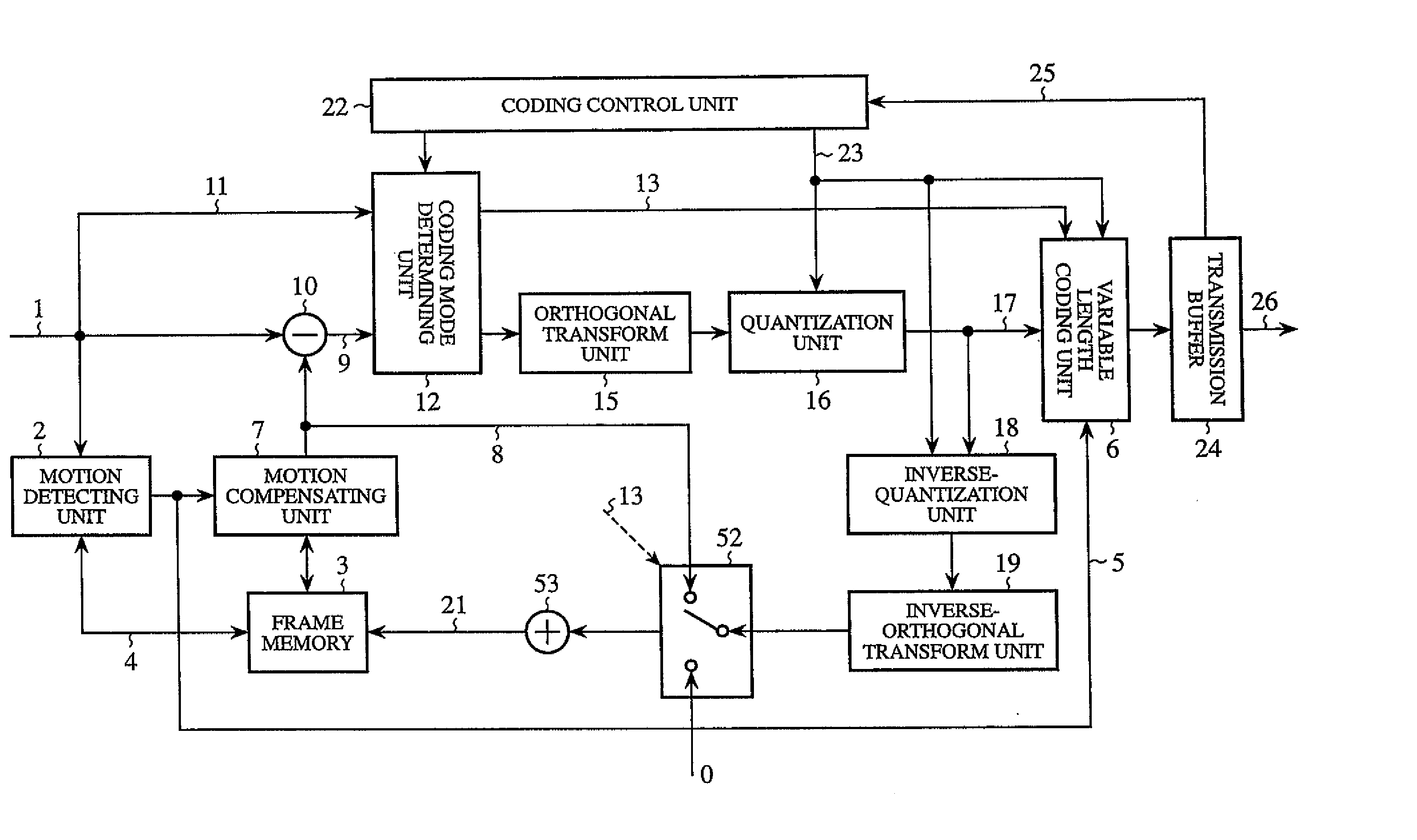
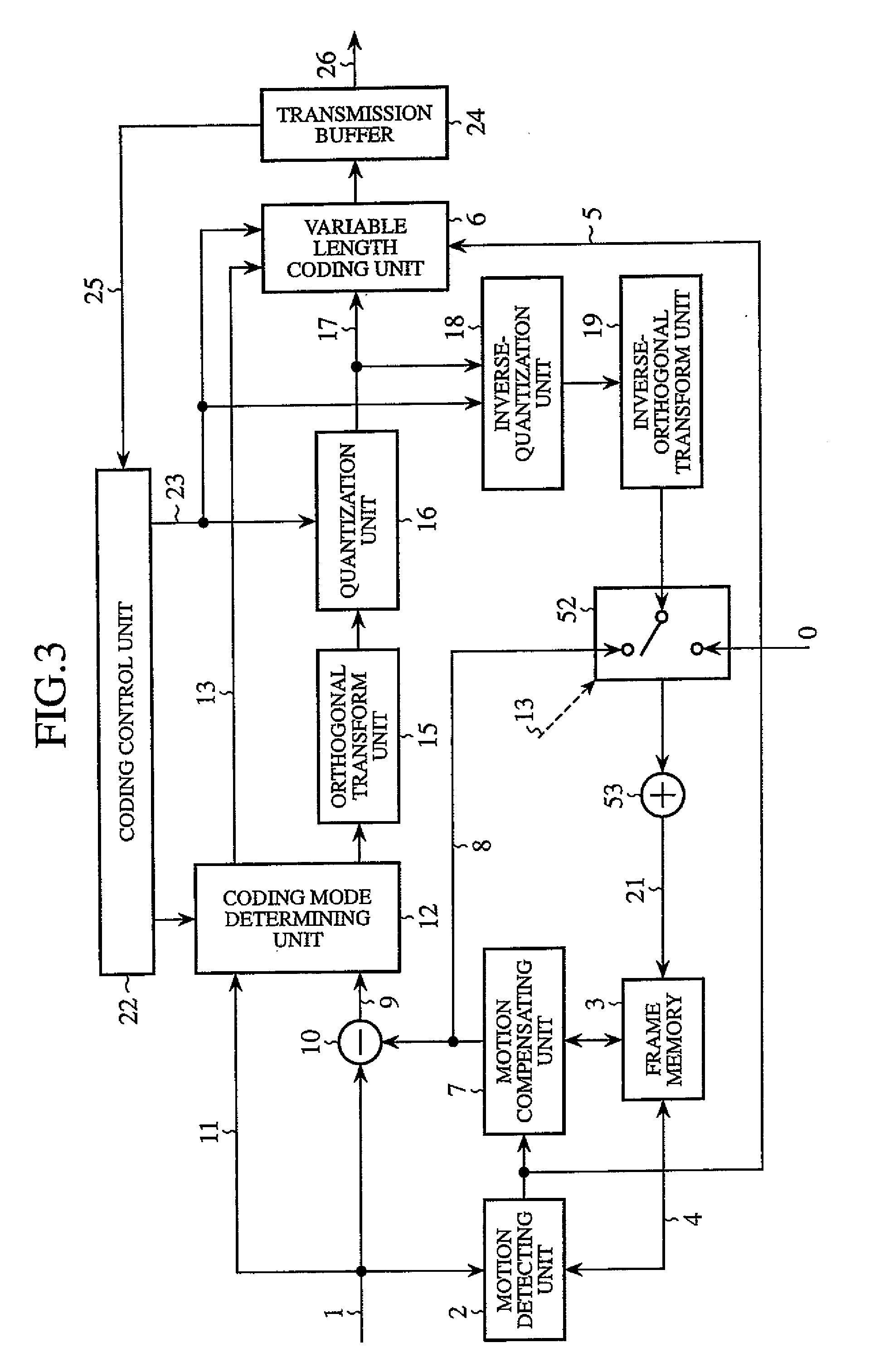
[0132]FIG. 10 shows the structure of the image coding apparatus in accordance with this embodiment 2. As shown in the figure, the image coding apparatus in accordance with this embodiment 2 differs from that of above-mentioned embodiment 1 as shown in FIG. 3 in that the frame memory 3 is replaced by the frame memory group 28, and a motion detecting unit 2 and a motion compensating unit 7 are so constructed as to use the frame memory group 28 to...

embodiment 3

[0155] In embodiment 3, an image coding apparatus and an image decoding apparatus respectively having a virtual sample calculation method switching flag with which the degree of freedom of adaptively switching between methods of calculating virtual samples in addition to the structures of the image coding apparatus and the image decoding apparatus in accordance with embodiment 1 or embodiment 2 will be explained.

[0156] Each of the image encoding apparatus and the image decoding apparatus as shown in embodiments 1 and 2 is so constructed as to perform motion compensated predictions only on virtual samples of half-pixel accuracy in a mode using blocks smaller than 8×8 MC, such as blocks of 8×4 size, blocks of 4×8 size, and blocks of 4×4 size, as shown in FIG. 6. According to a video image to be processed, there are cases in which each of the image coding apparatus and the image decoding apparatus needs to perform motion compensated predictions having ¼-pixel accuracy in order to impr...


PUM


Abstract

Each of an image coding apparatus and an image decoding apparatus uses a motion compensated prediction using virtual samples so as to detect a motion vector for each of regions of each frame of an input signal. Accuracy of virtual samples is locally determined while the accuracy of virtual samples is associated with the size of each region which is a motion vector detection unit in which a motion vector is detected. Virtual samples having half-pixel accuracy are used for motion vector detection unit regions having a smaller size 8×8 MC, such as blocks of 8×4 size, blocks of 4×8 size, and blocks of 4×4 size, and virtual samples having ¼-pixel accuracy are used for motion vector detection unit regions that are equal to or larger than 8×8 MC in size.

Description

[0001] This application is a Divisional of co-pending application Ser. No. 10 / 488,229 filed on Mar. 2, 2004, and for which priority is claimed under 35 U.S.C. § 120; and this application claims priority of Application No. PCT / JP03 / 07995 filed on Jun. 24, 2003 under 35 U.S.C. § 119; the entire contents of all are hereby incorporated by reference.FIELD OF THE INVENTION [0002] The present invention relates to an image coding apparatus for and an image coding method of, when encoding a picture with a high degree of efficiency, predicting a picture that should be encoded from an existing picture and encoding a prediction error, and an image decoding apparatus for and an image decoding method of, when encoding or decoding a picture or a coded picture with a high degree of efficiency, predicting a picture that should be reconstructed from an existing picture and decoding a coded picture by adding it to a prediction error. It also relates to a communication apparatus provided with at least ...

Claims


Application Information

Patent Timeline
Patent Type & Authority Applications(United States)
IPC IPC(8): H04N7/26H03M7/36H04N7/12H04N19/102H04N19/103H04N19/105H04N19/115H04N19/119H04N19/126H04N19/136H04N19/137H04N19/139H04N19/152H04N19/159H04N19/172H04N19/174H04N19/176H04N19/196H04N19/423H04N19/46H04N19/463H04N19/50H04N19/503H04N19/51H04N19/513H04N19/517H04N19/52H04N19/523H04N19/543H04N19/58H04N19/60H04N19/61H04N19/70H04N19/80H04N19/91
CPCH04N19/105H04N19/52H04N19/159H04N19/176H04N19/61H04N19/107H04N19/59H04N19/117H04N19/124H04N19/152H04N19/154H04N19/523H04N19/57H04N19/109
Inventor SEKIGUCHI, SHUNICHIYAMADA, YOSHIHISAASAI, KOHTARO
Owner MITSUBISHI ELECTRIC CORP
Why Eureka
Try Eureka