Efficient continuous flow irrigation endoscope

a continuous flow, endoscopy technology, applied in the field of endoscopy, can solve the problems of increased surgical time, increased risk of perforation, and large size of tissue pieces, and achieve the effect of increasing the surgical time, reducing the risk of perforation, and increasing the risk of bleeding excessively

Active Publication Date: 2008-04-17
KUMAR BV
View PDF25 Cites 46 Cited by
  • Summary
  • Abstract
  • Description
  • Claims
  • Application Information

AI Technical Summary

Benefits of technology

[0011]An object of the invention is to provide a continuous flow irrigation endoscope system in which the detached tissue pieces and waste fluid present inside a tissue cavity are evacuated in a continuous manner from the tissue cavity, without the need of removing the entire endoscope or a part of the endoscope from the tissue cavity.

Problems solved by technology

One disadvantage is that detached tissue pieces, larger than a critical size, present in the tissue cavity are unable to pass through the potential space between the outer and the inner sheaths.
Thus, in endoscopic procedures the entire endoscope or the “endoscopic instrument” has to be repeatedly removed from the tissue cavity in order to evacuate the detached tissue pieces present inside the tissue cavity, and this increases the risk of complications like perforation, excessive bleeding and also increases the surgical time.
However, such an arrangement is not desirable since it necessitates the incorporation of two out flow channels instead of one and it also tends to increase the overall weight of the endoscope.
The other disadvantage is that the inner sheath, by virtue of occupying additional space, reduces the effective lumen diameter of the endoscope which necessitates a reduction in the thickness or size of the “endoscopic instrument” or the telescope or both.

Method used


Image

  • Efficient continuous flow irrigation endoscope
  • Efficient continuous flow irrigation endoscope

Examples


Embodiment Construction

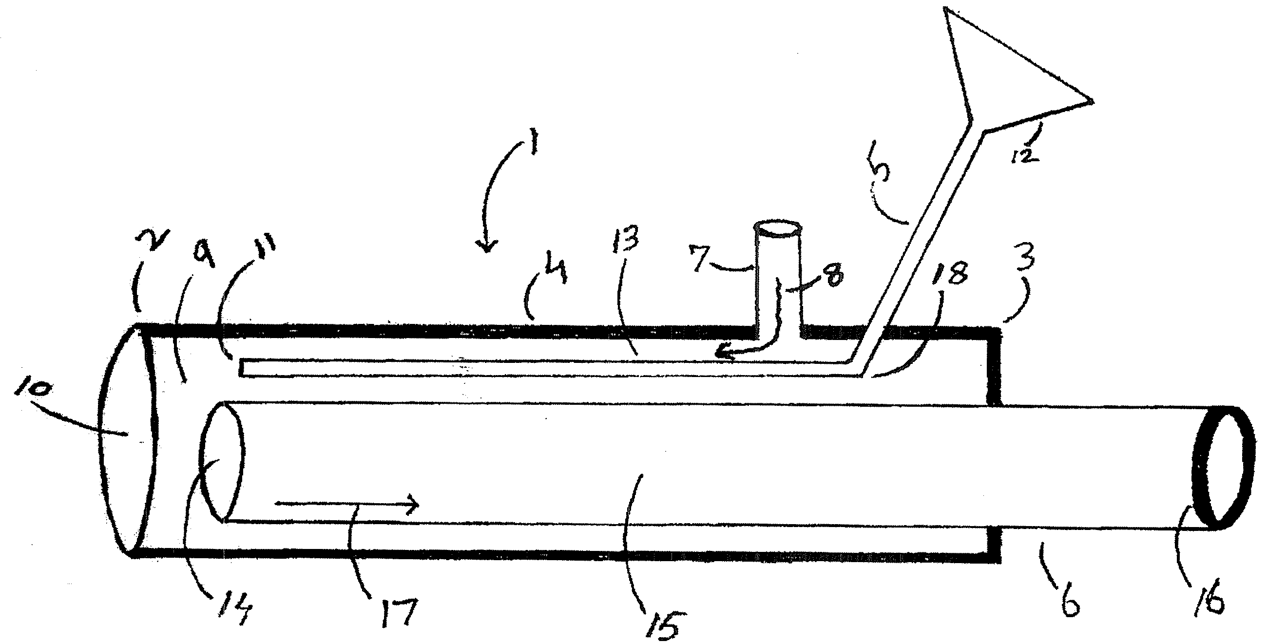
[0021]The present invention relates to a continuous flow irrigation endoscope in which the detached tissue pieces and waste fluid present inside a tissue cavity are automatically evacuated, in a continuous manner, without withdrawing the endoscope or any part of the endoscope from the tissue cavity.

[0022]The basic layout of the invented endoscope is shown in FIG. 1. The endoscope 1 has a distal end 2 which enters a tissue cavity and a proximal end 3 which lies outside the tissue cavity. The invented endoscope comprises an externally located “housing sheath”4, an optical system 5 and a hollow cylindrical tube like instrument 6.

[0023]Again referring to FIG. 1, unlike many prior art systems, the invented system does not have a separate inner sheath, and a single sheath has been termed as “housing sheath”4. The housing sheath 4 has an inflow port 7 located near its proximal end 3. Sterile irrigation fluid meant for distending a body tissue cavity is instilled via the inflow port 7 in th...


PUM


Abstract

A user friendly, safe and efficient continuous flow irrigation endoscope having only a single housing sheath without an inner sheath. The exclusion of the inner sheath increases the effective lumen of the endoscope. A long hollow cylindrical tube, capable of performing a to and fro and rotary motion, is placed inside the housing sheath to function as an endoscopic instrument, but also to serve as a conduit for evacuating waste fluid and detached tissue pieces present inside a tissue cavity. A single inflow port located at the proximal end of the single housing sheath allows the irrigation fluid to enter the tissue cavity via the lumen of the said housing sheath. The invented endoscope system has a single inflow port, a single outflow port, without an inner sheath so that all waste fluid and tissue debris present inside cavity are evacuated via the same single outflow port. No type of feedback mechanism, such as mechanical or electrical feedback mechanism, is incorporated in the endoscope to facilitate the removal of detached tissue pieces or waste fluid.

Description

CROSS-REFERENCE TO RELATED APPLICATIONS[0001]The present application claims the benefit of Indian Provisional Patent Application No. 2236 / DEL / 2006, filed on Oct. 11, 2006, the entire disclosure of which is incorporated by reference herein.FIELD OF THE INVENTION[0002]The present invention relates to surgeries and, in particular, to endoscopic procedures which deploy continuous flow irrigation, such as hysteroscopic fibroid morcellation, trans uretheral prostate morcellation, hysteroscopic polyp morcellation, hysteroscopic septoplasty, hysteroscopic adhesiolysis, trans uretheral morcellation of bladder tumors and arthroscopy.BACKGROUND OF THE INVENTION[0003]Continuous flow endoscopes are frequently used in endoscopic procedures such as hysteroscopy, trans uretheral urologic endoscopic procedures and arthroscopy. Those skilled in the art would know the structural composition of a continuous flow irrigation endoscope. In this application, the term “continuous flow irrigation” means that...

Claims


Application Information

Patent Timeline
Patent Type & Authority Applications(United States)
IPC IPC(8): A61B1/12
CPCA61B1/00071A61B1/012A61B17/320016A61M1/0058A61B2019/5217A61B2217/005A61B2217/007A61B17/32002A61B2090/3614A61B1/126A61B2017/320024
Inventor KUMAR
Owner KUMAR BV
Why Eureka
Try Eureka