Apparatus for Cosmetic Skin Rejuvenation Treatment

a skin rejuvenation and cosmetic technology, applied in the field of cosmetic skin rejuvenation treatment, can solve the problems of too high cost of consumer applications, less effective than professional devices, etc., and achieve the effect of reducing wrinkles and facilitating the design of relatively inexpensive consumer devices for skin rejuvenation treatmen

a skin rejuvenation and cosmetic technology, applied in the field of cosmetic skin rejuvenation treatment, can solve the problems of too high cost of consumer applications, less effective than professional devices, etc., and achieve the effect of reducing wrinkles and facilitating the design of relatively inexpensive consumer devices for skin rejuvenation treatmen

US20080215124A1Inactive Publication Date: 2008-09-04KONINKLIJKE PHILIPS ELECTRONICS NV

Image

  • Apparatus for Cosmetic Skin Rejuvenation Treatment
  • Apparatus for Cosmetic Skin Rejuvenation Treatment
  • Apparatus for Cosmetic Skin Rejuvenation Treatment

Examples


Embodiment Construction

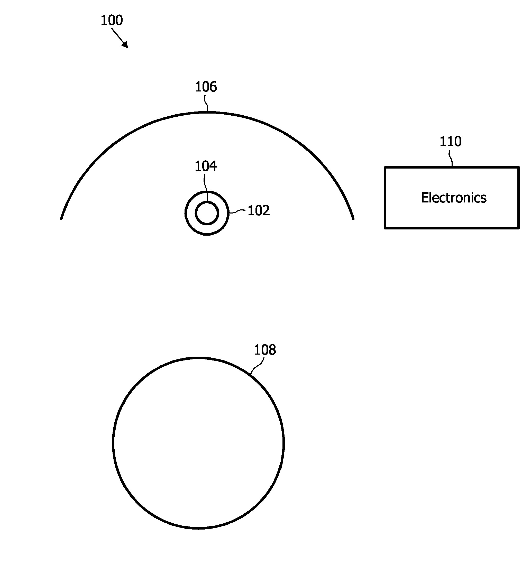
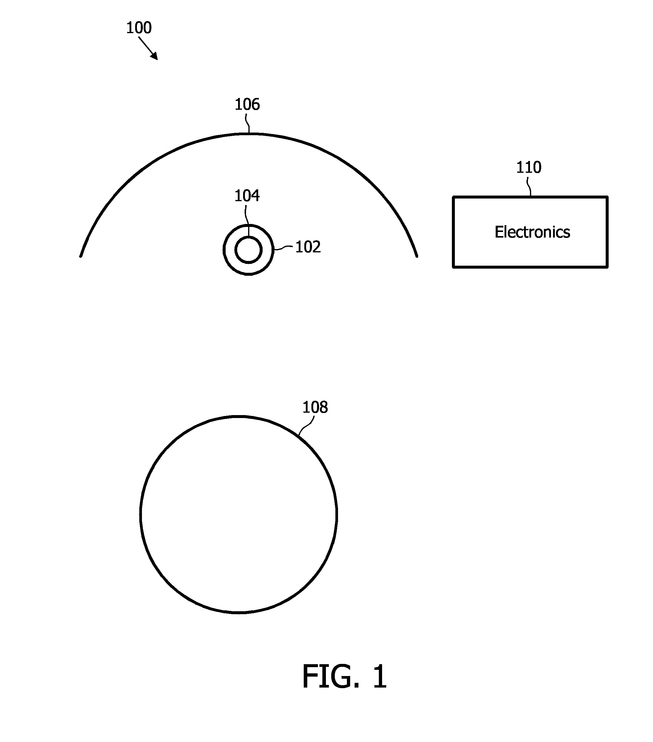
[0035]FIG. 1 shows an apparatus 100 for cosmetic skin rejuvenation treatment. The apparatus has a continuous wave light source comprising a socket 102 for receiving a high-intensity discharge lamp 104. The high-intensity discharge lamp 104 is positioned in a focal area of a reflector 106. The reflector 106 concentrates and directs the light emitted from the high-intensity discharge lamp 104 towards a person 108 who is sitting in front of the apparatus 100. The operation of the apparatus 100 is controlled by an electronics module 110 which has also a current-limiting function for operation of the high-intensity discharge lamp 104. This current-limiting function can be implemented as an inductor, a transformer ballast or, alternatively, by using an electronic lamp driver module operating with a square-wave current profile or a high-frequency sinusoidal current profile.

[0036]The high-intensity discharge lamp 104 has a predominant spectral peak between 550 and 700 nm.

[0037]The skin of t...


PUM


Abstract

The present invention relates to an apparatus for cosmetic skin rejuvenation treatment, comprising a continuous wave light source accommodating a high-intensity discharge lamp (104; 204; 304; 604) which has at least one predominant spectral peak between 600 and 700 nm.

Description

FIELD OF THE INVENTION[0001]The present invention relates to the field of phototherapy of the skin.BACKGROUND OF THE INVENTION[0002]Skin rejuvenation treatments are performed nowadays in the professional sector with lasers or IPL (Intense Pulsed Light), which are either ablative, i.e. they burn a layer of the skin, starting a wound healing process which leads to formation of new collagen so that the skin looks younger, or which are non ablative, stimulating the collagen production without burning the skin (in this case the treatment is called just “wrinkles reduction”). For acne treatment, lasers or IPL give enough energy to effectively kill de acne bacteria or destroy the sebaceous glands.[0003]There is a recent trend in the professional market to go to lower energy therapies, with a continuous light source like LEDs, which could be use alone or in synergy with an IPL or laser treatments. But, especially for the consumer market a low energy light source is mandatory, for safety rea...

Claims


Application Information

Patent Timeline
04 Sep 2008
Publication
US20080215124A1
IPC
A61N5/06; A61B18/18
CPC
A61B18/203; A61B2018/00452; A61N5/0616; A61B2018/1807; A61B2018/0047
Inventors
WAGENAAR CACCIOLA, GIOVANNA; FISCHER, VINCENT