Coil-driving apparatus of electronic magnetic contactor

a technology of electronic magnetic contactor and coil drive, which is applied in the direction of electrical apparatus, operation facilitation, and electrical relay details, etc., can solve the problems of increasing defect generation rate, complicated circuits, and errors due to analog components, so as to reduce the number of analog components, minimize power consumption, and reduce the effect of malfunction and error generation ra

Active Publication Date: 2008-09-11
LS IND SYETEMS CO LTD
View PDF4 Cites 23 Cited by
  • Summary
  • Abstract
  • Description
  • Claims
  • Application Information

AI Technical Summary

Benefits of technology

[0031]As specifically described as above, with the present invention, the main units in an analog scheme, for generating PWM signals, are replaced by a PWM controller of low power consumption to reduce the number of the analog components and minimize power consumption. Furthermore, it is feedback with the current flowing on a coil to control constant current to be flown on the coil.
[0032]Therefore, it has effects to reduce malfunction and error generation rate by preventing deterioration and burning of components.
[0033]Finally, it has effects to implement a small-sized coil-driving apparatus of an electronic magnetic contactor having a high durability and reliability.

Problems solved by technology

First, circuits become complicated due to the components of the respective units, and a circuit board becomes large for inserting the components into the circuit substrate to that extent.
Also, errors occur due to use of the analog components and defect generation rate increases due to multiple analog components.
Also, current consumed in the circuit becomes large to generate much heat thereby the components are deteriorated or burnt.
However, these problems have not been easily solved due to expenses, power consumption and other reasons.

Method used


Image

  • Coil-driving apparatus of electronic magnetic contactor
  • Coil-driving apparatus of electronic magnetic contactor
  • Coil-driving apparatus of electronic magnetic contactor

Examples


Embodiment Construction

[0037]Hereinafter, the present novel concept will be described in detail with reference to the accompanying drawings.

[0038]However, in describing the present invention, specific description thereof will be omitted, when it is judged that the specific description of the relevant well-known function or constitution may make the gist of the present description obscure.

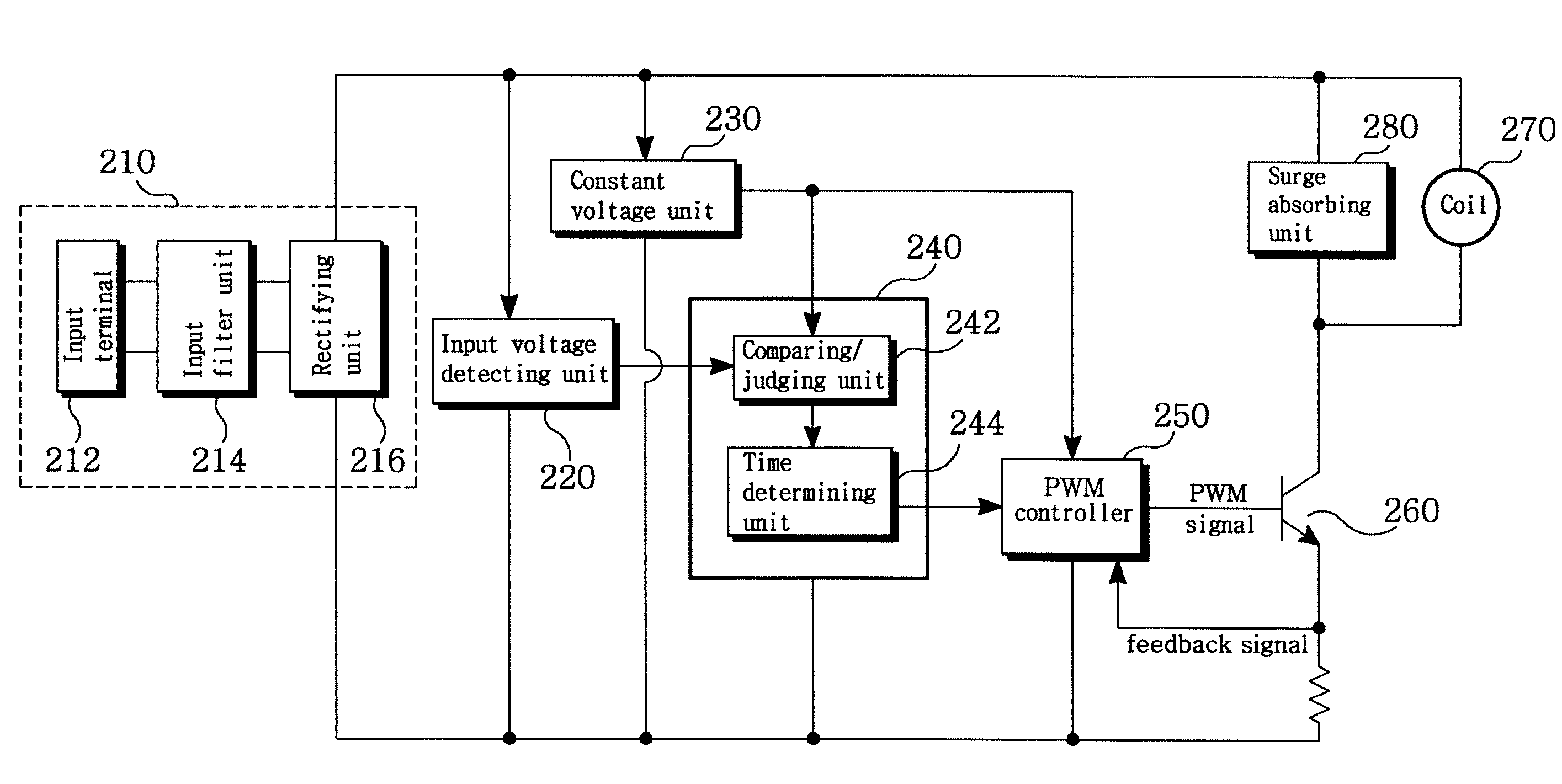
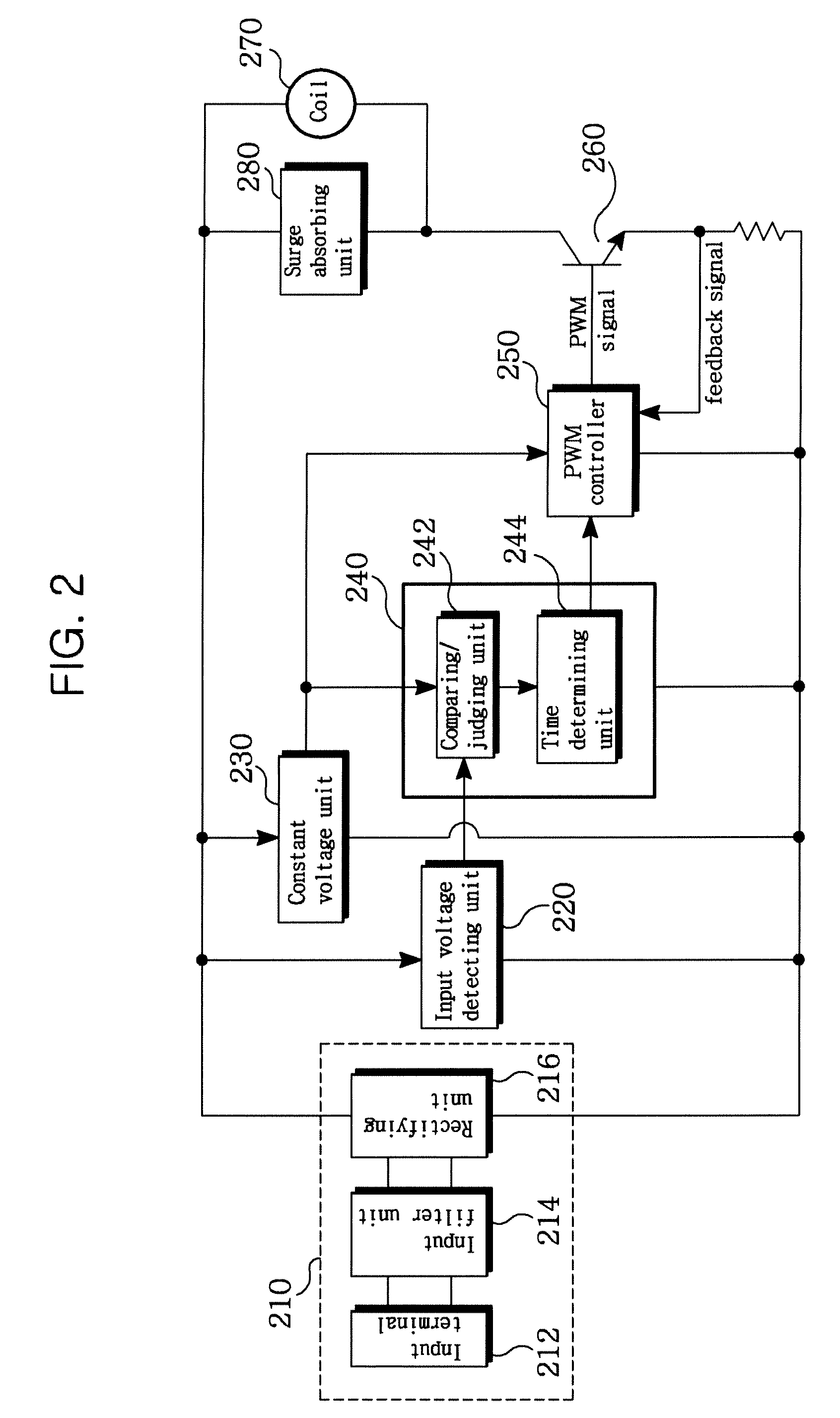
[0039]FIG. 2 is a block diagram showing a constitution of a coil-driving apparatus of an electronic magnetic contactor, and FIG. 3 is an exemplary circuit constitution of the PWM controller of FIG. 2.

[0040]Referring to FIG. 2, the coil-driving apparatus of the electronic magnetic contactor largely comprises: a voltage detecting unit 200; and a driving control unit 290, wherein the voltage detecting unit specifically includes an input power processing unit 210 and an input voltage detecting unit 220, and the driving control unit 290 includes an operation control unit 240 and a PWM controller 250. In addition, the coil-driv...


PUM


Abstract

A coil-driving apparatus of an electro magnetic contactor is disclosed, which replaces the main units in an analog scheme with those in a digital scheme using a PWM controller of low power consumption to reduce the number of the analog components, minimize power consumption, and controls a constant voltage that flows on the coil by receiving the feedback current flowing on the coil, whereby error and defect generation rates are reduced, and deterioration and burning of components are prevented.

Description

CROSS-REFERENCE TO RELATED APPLICATION[0001]The present application is based on, and claims priority from, Korean Application Number 10-2007-0021272 filed Mar. 5, 2007, the disclosure of which is incorporated herein by reference in its entirety.BACKGROUND OF THE INVENTION[0002]This description relates to a coil-driving apparatus of electronic magnetic contactor, and more particularly to a coil-driving apparatus of electronic magnetic contactor changing circuit units in an existing analog scheme into those in a digital scheme by means of a PWM (Pulse Width Modulation) controller of low power consumption to reduce the number of analog components and to minimize power consumption.[0003]Generally, an electronic magnetic contactor, which is an apparatus connected to an electrical connection path to supply or block power to a load in a system such as a building, a factory, and a ship, etc., prevents the load from being burnt out.[0004]The electronic magnetic contactor, which is equipment ...

Claims


Application Information

Patent Timeline
Patent Type & Authority Applications(United States)
IPC IPC(8): H01H47/00
CPCH01H47/325H01H50/443H01H50/58H01H2047/046H01H2217/046
Inventor BAEK, SEUNG MOON
Owner LS IND SYETEMS CO LTD
Why Eureka
Try Eureka