Scrap melter and impeller therefore

a technology of scrap melter and impeller, which is applied in the direction of manufacturing converters, furniture, lighting and heating apparatus, etc., can solve the problems of reducing the efficiency of scrap melting operation, clogging of scrap impeller, and reducing the flow of virgin fluid through the impeller, so as to reduce jamming or clogging, reduce problems, and accelerate the effect of operation speed

Inactive Publication Date: 2008-09-25
COOPER PAUL V
View PDF103 Cites 88 Cited by
  • Summary
  • Abstract
  • Description
  • Claims
  • Application Information

AI Technical Summary

Benefits of technology

[0007]The preferred embodiment of the present invention is a scrap melter utilizing an open impeller to reduce jamming or clogging. Thus, the invention can function efficiently in virtually any scrap melting environment, handling particles of virtually any size that are likely to be encountered in any such environment. An impeller according to the invention functions by displacing molten metal to create a downward draw. It provides t...

Problems solved by technology

However, such impellers can create turbulence or flow that may partially move into the path of the fluid entering the impeller from above, in which case some scrap may not be efficiently drawn into bath B where it can be melted and mixed, thus decreasing the fluid flow to the impeller and decreasing the efficiency of the scrap melting operation.
In addition, the radial turbulence may cause some fluid that has been expelled from the impeller to be ...

Method used


Image

  • Scrap melter and impeller therefore
  • Scrap melter and impeller therefore
  • Scrap melter and impeller therefore

Examples


Embodiment Construction

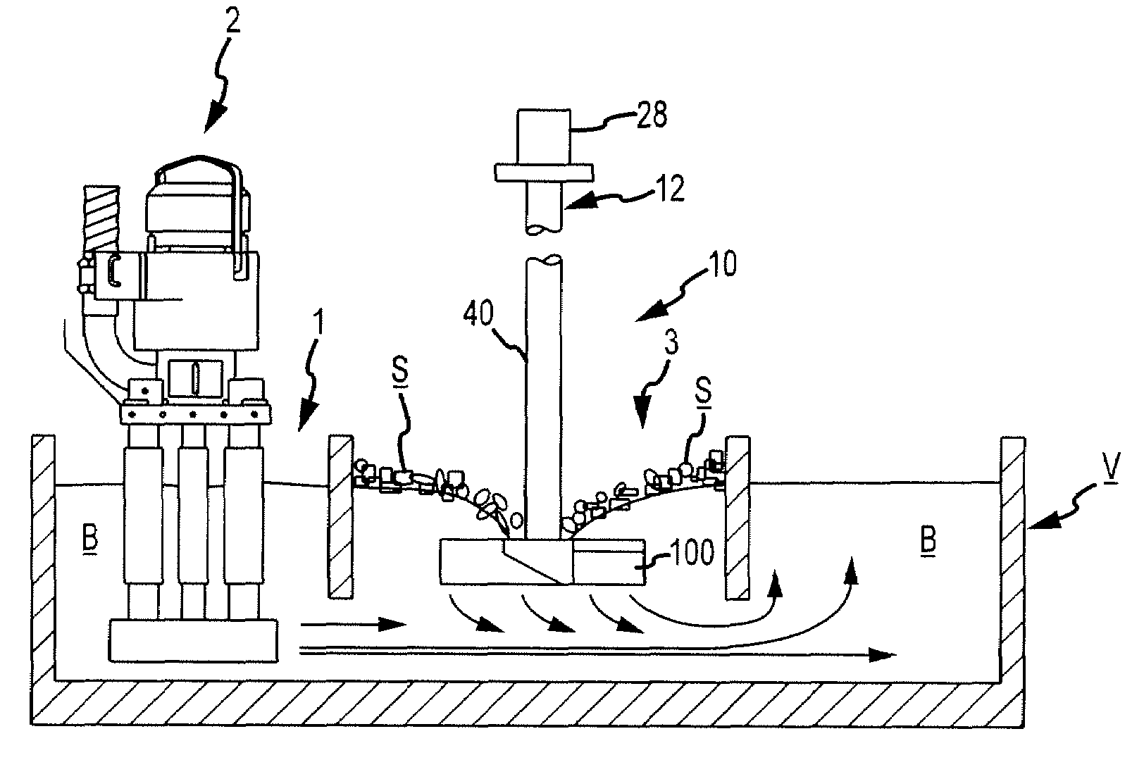
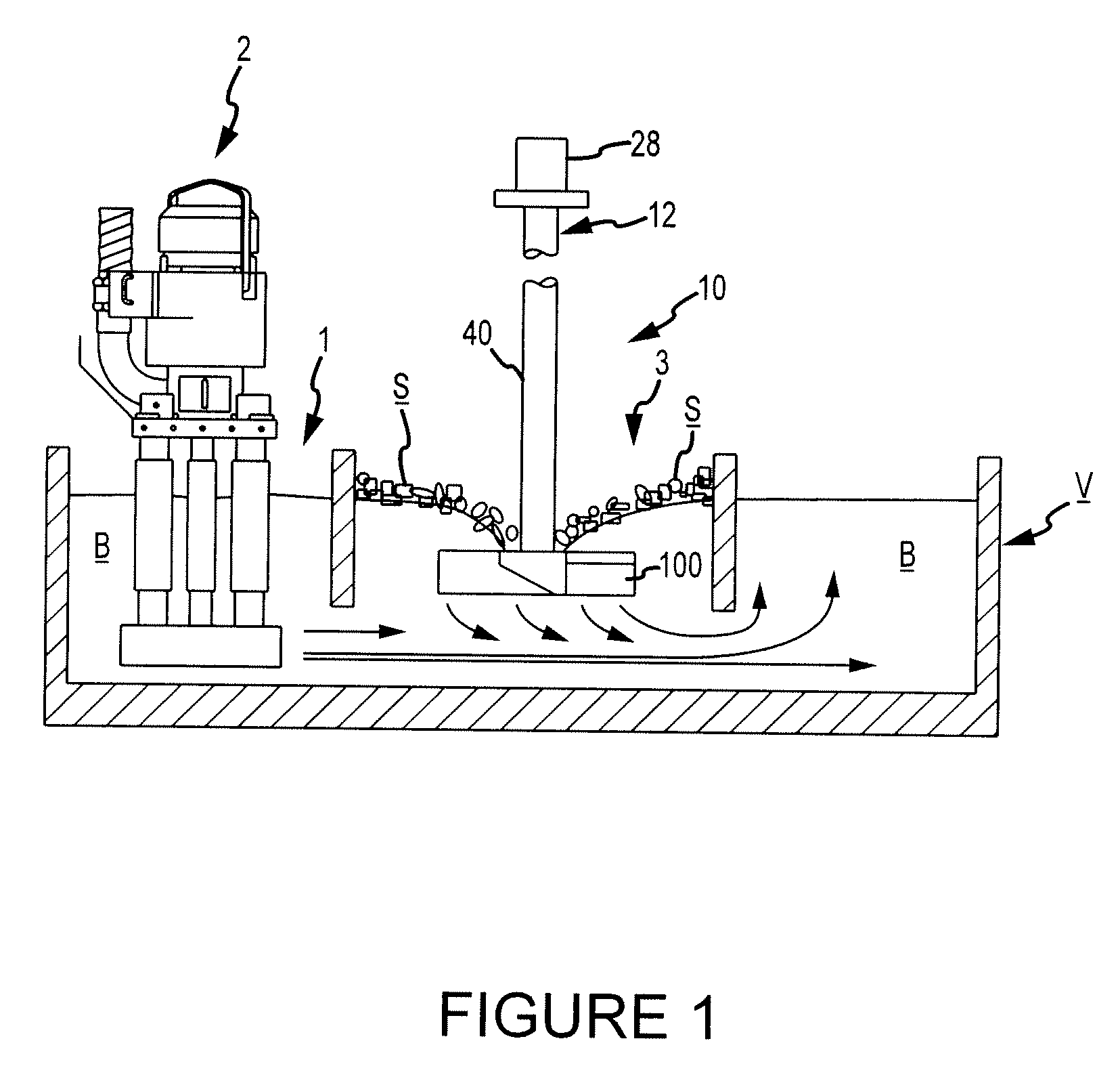
[0021]Referring now to the figures, where the purpose is for describing a preferred embodiment of the invention and not for limiting same, FIG. 1 shows a scrap melter 10 submerged in a molten metal bath B. All of the components of scrap melter 10 exposed to molten metal bath B are preferably formed from oxidation-resistant graphite or other material suitable for use in molten metal.

[0022]A drive source 28 is connected to impeller 100 by any structure suitable to transfer driving force from source 28 to impeller 100. Drive source 28 is preferably an electric, pneumatic or hydraulic motor although, as used herein, the term drive source refers to any device or devices capable of rotating impeller 100.

[0023]A drive shaft 12 is preferably comprised of a motor drive shaft (not shown) connected to an impeller drive shaft 40. The motor drive shaft has a first end and a second end, the first end being connected to motor 28 by any suitable means and which is effectively the first end of drive...


PUM

PropertyMeasurementUnit
Angleaaaaaaaaaa
Heightaaaaaaaaaa
Heightaaaaaaaaaa

Abstract

A device for submerging scrap metal includes: (a) a drive source, (b) a drive shaft having a first end and a second end, the first end being connected to the drive source, and (d) an impeller connected to the second end of the drive shaft, the impeller preferably having two or more outwardly-extending blades. Preferably, each of the blades has a portion that directs molten metal at least partially downward. The impeller design leads to lower operating speeds, lower vibration, longer component life and less maintenance. Additionally, the impeller preferably has a connective portion. The connective portion is used to connect the impeller to the shaft and preferably comprises a nonthreaded, tapered bore extending through the impeller.

Description

RELATED APPLICATIONS[0001]This application is a continuation of and claims priority to U.S. application Ser. No. 10 / 827,941 filed Apr. 19, 2004, which is a divisional application of and claims priority to U.S. patent application Ser. No. 09 / 649,190, filed Aug. 28, 2000, now U.S. Pat. No. 6,723,276.FIELD OF THE INVENTION[0002]The present invention relates to a device, called a scrap melter, for submerging scrap metal in a molten metal bath. The device preferably includes a drive source, an impeller and a drive shaft. The device preferably draws molten metal downward in order to submerge scrap placed on the surface of the bath.BACKGROUND OF THE INVENTION[0003]Scrap melter systems, such as the one shown schematically in FIGS. 1 and 2, generally use two devices, a circulation pump and a scrap melter. As shown in FIG. 1 the vessel V containing molten metal bath B is preferably divided into two compartments. Compartment 1 (called a pump well) houses circulation pump 2. Compartment 3 (call...

Claims


Application Information

Patent Timeline
IPC IPC(8): B22D41/005B22D41/00C21C1/06C21C5/52F27B3/04F27D27/00
CPCC21C1/06C21C5/5211C21C5/527F27D27/00F27B3/045Y02P10/20
Inventor COOPER, PAUL V.
Owner COOPER PAUL V
Why Eureka
Try Eureka