Dynamically Configuring and Selecting Multiple Ray Tracing Intersection Methods

a ray tracing intersection and dynamic selection technology, applied in the field of computer processing, can solve the problems of rasterization suffering from some drawbacks, modern monitors display images, and use relatively low amounts of computational power

Active Publication Date: 2008-10-23
ACTIVISION PUBLISHING
View PDF2 Cites 61 Cited by
  • Summary
  • Abstract
  • Description
  • Claims
  • Application Information

AI Technical Summary

Benefits of technology

[0016]According to another embodiment of the invention a method of generating a spatial index is provided. The method generally comprising: partitioning a three-dimensional scene by drawing splitting planes along axes in a world coordinate system and creating nodes in the spatial index which correspond to bounding volumes created by the splitting planes; partitioning a portion of the three-dimensional scene by drawing splitting planes along axes in a object coordinate system and creating nodes in the spatial index which correspond to bounding volumes created by the splitting planes, wherein the portion of the three-dimensional scene bounds one or more dynamic objects; creating a branch from a node corresponding to a bounding volume created by a splitting plane along an axis in the world coordinate system to a node corresponding to a bounding volume created by one or more splitting planes in the object coordinate system; and determining whether or not to convert coordinates of one or more primitives which make up an object from th

Problems solved by technology

One limitation of rendering realistic images is that modern monitors display images through the use of pixels.
Rasterization is effective at rendering graphics quickly and using relatively low amounts of computational power; however, rasterization suffers from some drawbacks.
For example, rasterization often suffers from a lack of realism because it is not based on the physical properties of light, rather rasterization is based on the shape of three-dimensional geometric objects in a scene projected onto a two-dimensional plane.
Furthermore, the computational power required to render a scene with rasterization scales directly with an increase in the complexity of the scene to be rendered.
As image processing becomes more realistic, rendered scenes also become more complex.
Therefore, rasterization suffers as image processing evolves, because rast

Method used


Image

  • Dynamically Configuring and Selecting Multiple Ray Tracing Intersection Methods
  • Dynamically Configuring and Selecting Multiple Ray Tracing Intersection Methods
  • Dynamically Configuring and Selecting Multiple Ray Tracing Intersection Methods

Examples


Embodiment Construction

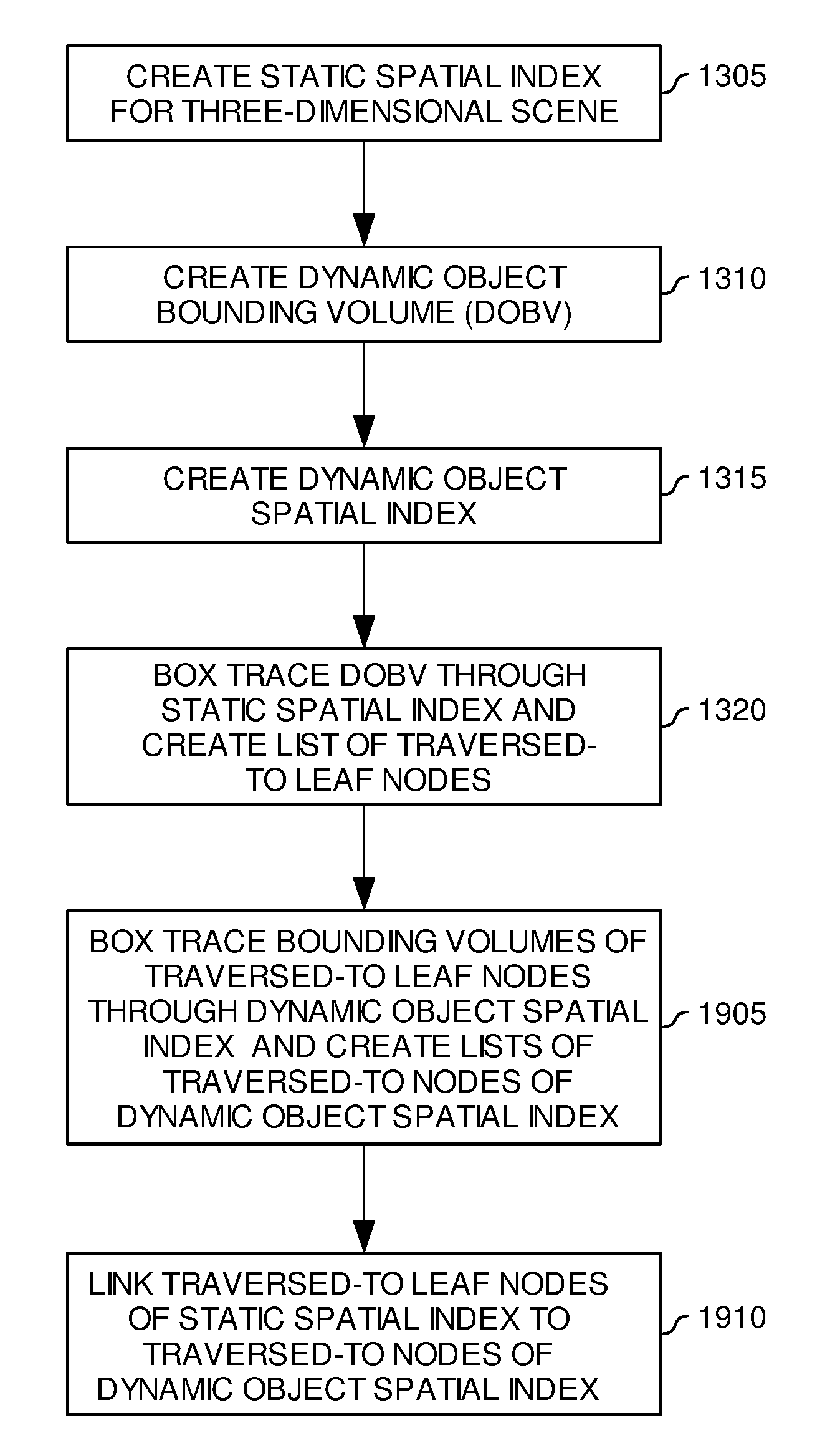
[0037]Embodiments of the invention provide methods and articles of manufacture for selecting a coordinate system to use when tracing rays through a portion of a spatial index which corresponds to a dynamic object. According to embodiments of the invention, an image processing system may assess various factors associated with a dynamic object to determine if a world coordinate system or an object coordinate system would be more efficient to use when performing ray tracing through a portion of the spatial index which corresponds to the dynamic object. The factors may include, but are not limited to, the size of the dynamic object, the distance of the dynamic object from a viewpoint, the distance of the dynamic object from the origin of the world coordinate system, a rate of traversal of the dynamic object, and a number of primitives which make up the dynamic object.

[0038]In the following, reference is made to embodiments of the invention. However, it should be understood that the inve...


PUM


Abstract

Embodiments of the invention provide methods and apparatus to determine a coordinate system to use when traversing rays through a portion of a spatial index corresponding to a dynamic object which has a unique object coordinate system. An image processing system may take into consideration a number of factors including, but not limited to, a distance form a viewpoint to the dynamic object, a distance from the origin of the world coordinate system to the object coordinate system, a rate of traversal of the dynamic object, and a number of primitives which make up the object. These factors alone or together may indicate whether it is more efficient to perform ray intersection tests in an object coordinate system or in a world coordinate system. Embodiments of the invention may update a spatial index according to the selected coordinate system.

Description

BACKGROUND OF THE INVENTION[0001]1. Field of the Invention[0002]Embodiments of the invention generally relate to the field of computer processing.[0003]2. Description of the Related Art[0004]The process of rendering two-dimensional images from three-dimensional scenes is commonly referred to as image processing. As the modern computer industry evolves image processing evolves as well. One particular goal in the evolution of image processing is to make two-dimensional simulations or renditions of three-dimensional scenes as realistic as possible. One limitation of rendering realistic images is that modern monitors display images through the use of pixels.[0005]A pixel is the smallest area of space which can be illuminated on a monitor. Most modern computer monitors will use a combination of hundreds of thousands or millions of pixels to compose the entire display or rendered scene. The individual pixels are arranged in a grid pattern and collectively cover the entire viewing area of ...

Claims


Application Information

Patent Timeline
IPC IPC(8): G06T15/40
CPCG06T15/06
Inventor FOWLER, DAVID KEITHSHEARER, ROBERT ALLEN
Owner ACTIVISION PUBLISHING
Why Eureka
Try Eureka