

Foil transfer apparatus
a transfer apparatus and transfer foil technology, applied in the direction of printing presses, thin material processing, printing, etc., can solve the problems of difficult to securely carry out foil saving, cracks, creases, etc., and difficult to adjust the tensile force of the transfer foil b>1/b>, so as to achieve secure foil saving and ease of stabilization of the tensile force of the transfer foil
- Summary
- Abstract
- Description
- Claims
- Application Information
AI Technical Summary
Benefits of technology
Problems solved by technology
Method used
Image

Examples
Embodiment Construction
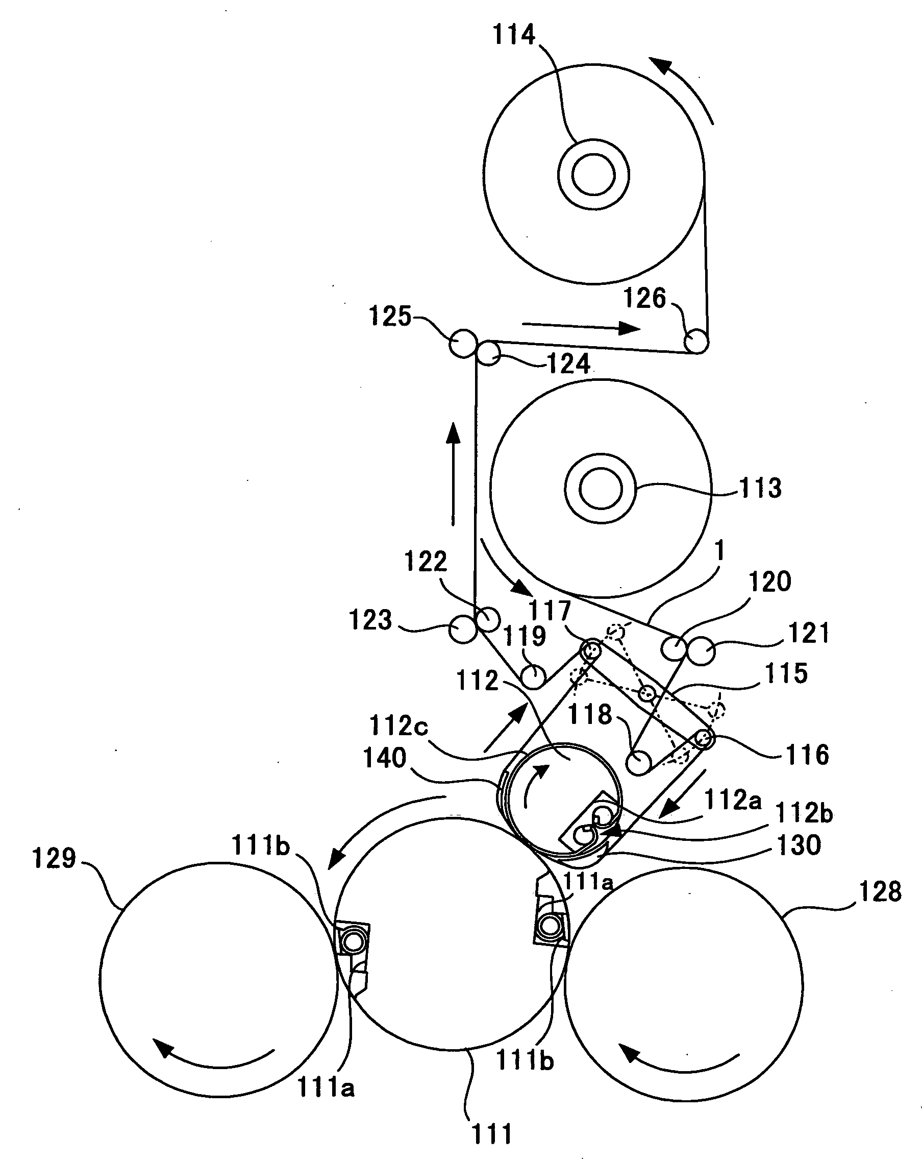
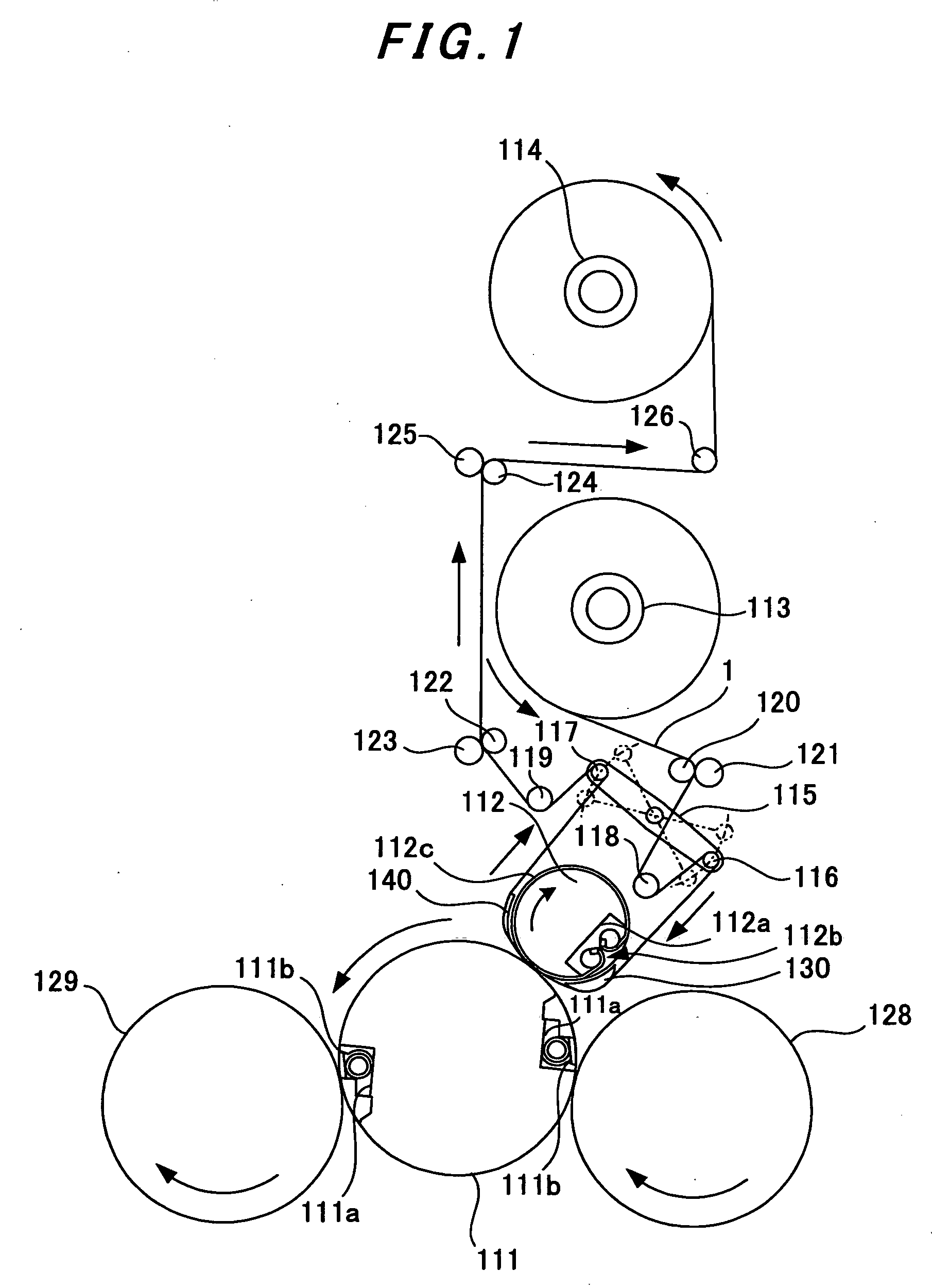
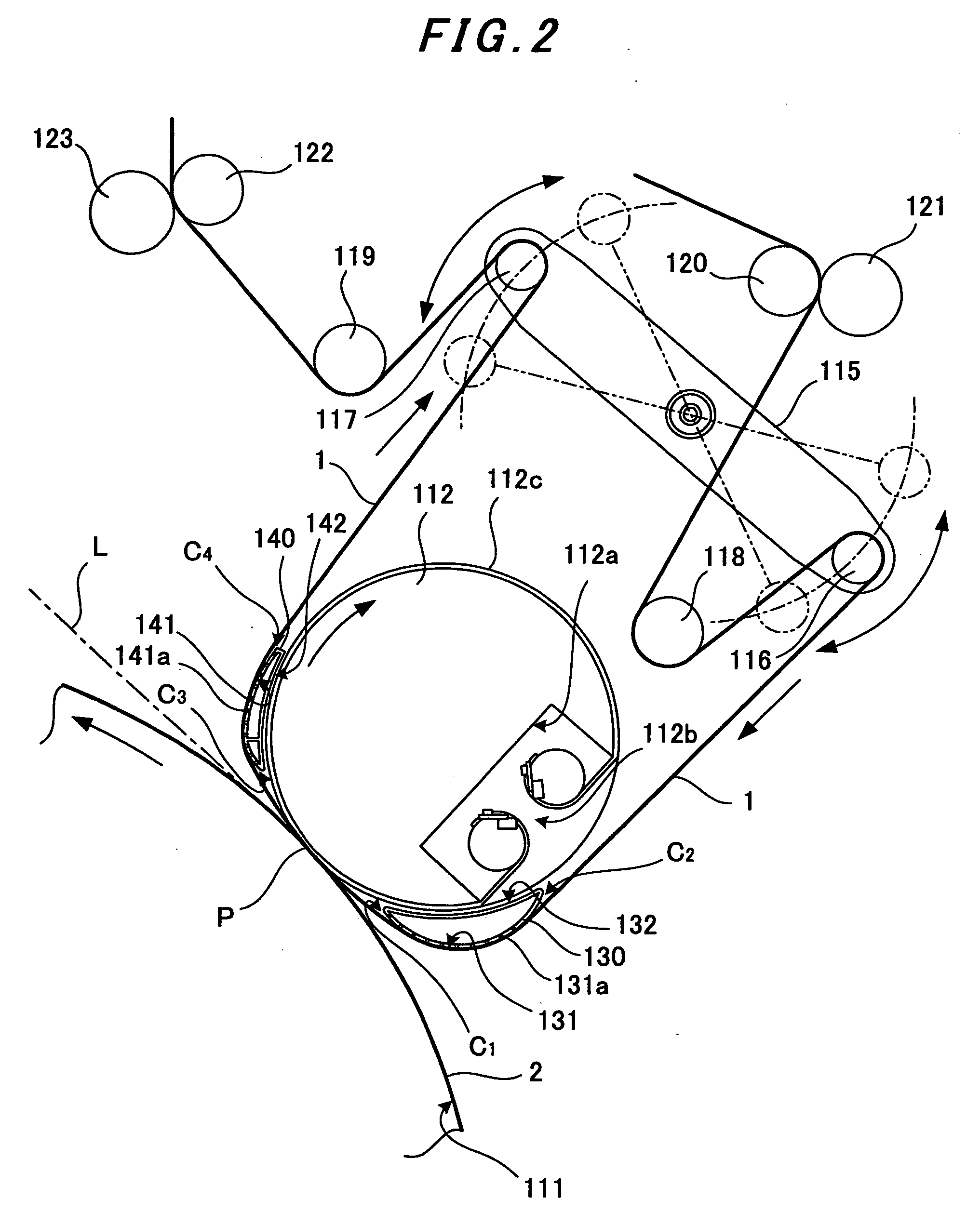
[0040]An embodiment in which the present invention is applied to a cold-foil-transfer type foil transfer apparatus will be described with reference to FIGS. 1 to 7.
[0041]FIGS. 1 to 3 show that a transfer cylinder 128 opposees a transport cylinder (an impression cylinder) 111. The transport cylinder 111 is a sheet-transport cylinder for supporting a sheet. To be more specific, the transport cylinder 111 supports a paper sheet 2, which is an example of the transfer-object sheet, on its outer circumferential surface. To this end, notch portions 111a are formed in the outer circumferential surface of the transport cylinder 111. A gripper device 111b is installed in each of the notch portions 111a, and holds the front-end side of the paper sheet 2. The transfer cylinder 128 transfers the paper sheet 2 from a feeder apparatus to the transport cylinder 111. Here, onto the paper sheet 2, adhesive agent that corresponds to a design has been transferred with an adhesive-agent transfer apparat...
PUM
| Property | Measurement | Unit |
|---|---|---|
| thickness | aaaaa | aaaaa |
| area | aaaaa | aaaaa |
| shape | aaaaa | aaaaa |
Abstract
Description
Claims
Application Information