Solar Energy Collection Device for Tiled Roofs, and a Method for Mounting the Same

a solar energy collection and tiled roof technology, applied in the direction of solar heat collectors with working fluids, solar heat collectors for particular environments, solar-ray concentration, etc., can solve the problems of corrosion of the elements of these types of panels, and the aesthetics of the architectural assembly over which the thermal solar panels are mounted

Inactive Publication Date: 2008-12-18
GIANASSO ROLAND +1
View PDF2 Cites 23 Cited by
  • Summary
  • Abstract
  • Description
  • Claims
  • Application Information

AI Technical Summary

Benefits of technology

[0014]A support cradle which facilitates the hermetic anchor of the heat exchanger to the heat transfer tube achieving optimum thermal use.
[0020]The bellows lifting device provided with its positioning slots or the means (special tool) of aligning and freeing the leaf spring, in its variation they allow, by downward manual pressure applied on the irregular transparent body, this to be connected to the support cradle hermetically sealing the heat transfer tube. This installation procedure similarly offers the greater advantage of achieving a solid assembly between the three elements that make up the tile, the irregular transparent body and the heat transfer tube, being able in this way to adequately support the thermal expansions of the roof in its assembly.
[0023]It has also been anticipated that the tube for transporting the heat transfer fluid passes through the inside part of the aforementioned hermetic body, improving its arrangement.

Problems solved by technology

This brings with it very considerable damage to the aesthetics of the architectural assembly over which the thermal solar panels are mounted, particularly when, as often happens, the surface and the panel colour and its visible accessories have absolutely nothing to do with the characteristics of the existing roof, particularly when it is a roof based on curved or mixed tiles, so common particularly in areas where solar radiation is abundant as well those situated below latitude 50° north.
To this aesthetic problem also has to be added the problems of corrosion that occur in the elements of these types of panels in the open air when the installations are situated near a marine environment.

Method used


Image

  • Solar Energy Collection Device for Tiled Roofs, and a Method for Mounting the Same
  • Solar Energy Collection Device for Tiled Roofs, and a Method for Mounting the Same
  • Solar Energy Collection Device for Tiled Roofs, and a Method for Mounting the Same

Examples


Embodiment Construction

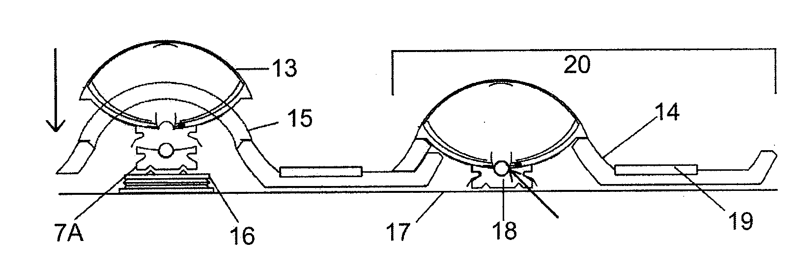
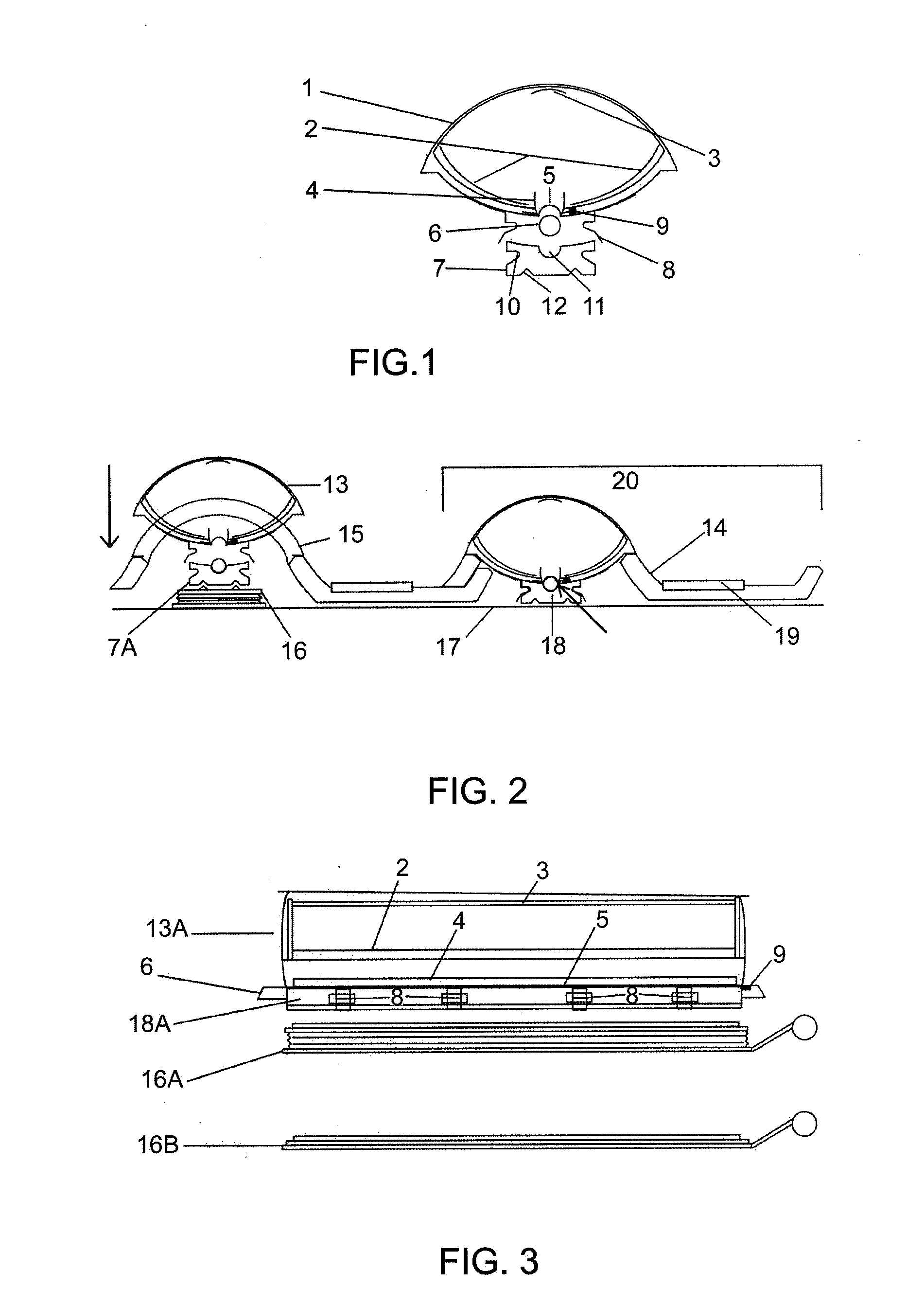
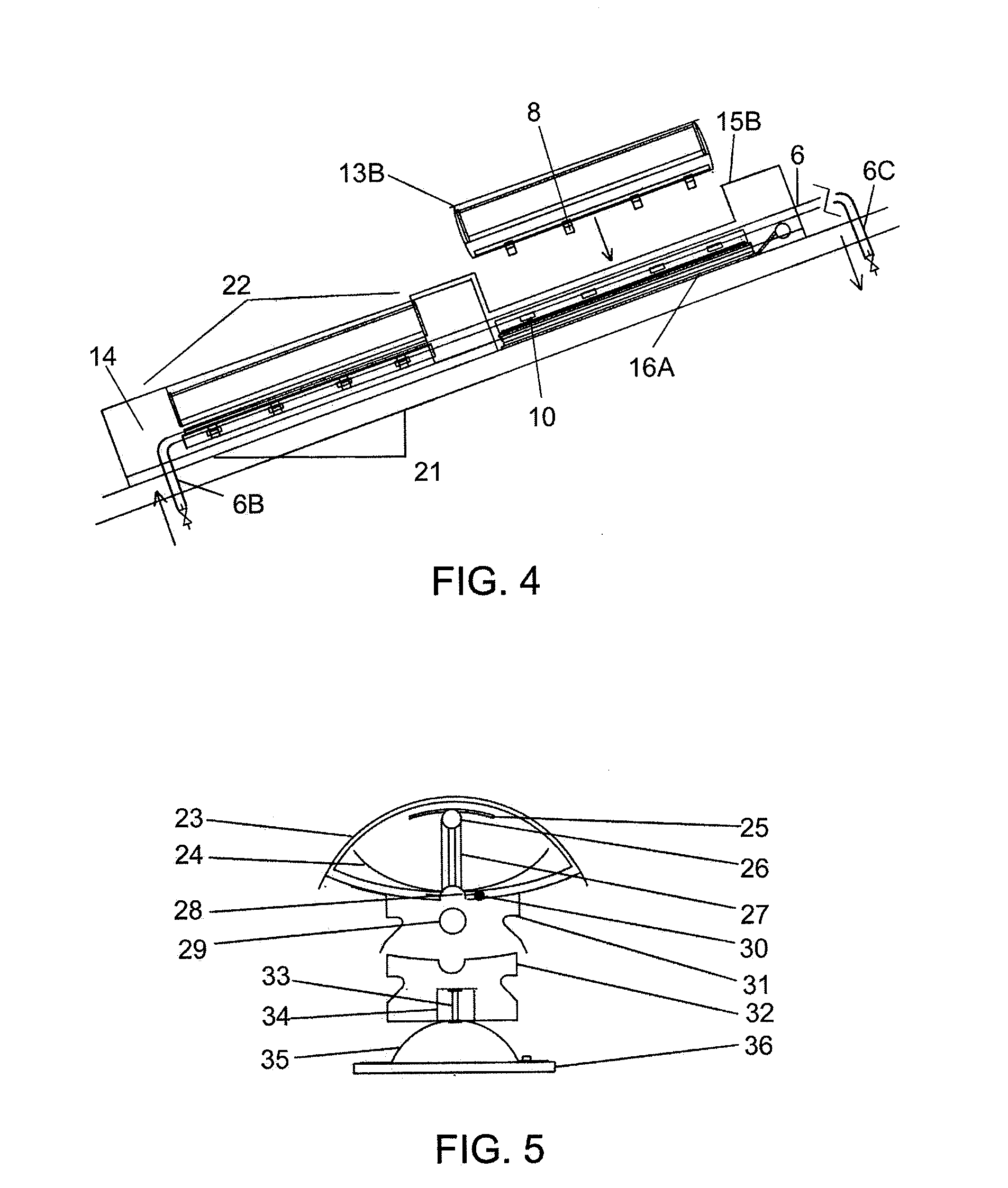
[0008]The invention fully satisfactorily resolves the previously explained problem, and from this it converts a traditional roof composed of curved or mixed conventional tiles into a similar and aesthetic configured surface, but which incorporates a device composed of different solar energy collection modules.

[0009]Thus, the device comprises the following basic elements:[0010]A four sided irregular body with a parabolic cylinder able to be attached to the vacuum filled receiver tiles in their interior space.[0011]A means of returning and concentrating the solar radiation.[0012]A heat exchanger adapted to the lower length of the energy collection device.[0013]A heat transfer fluid channelling tube that allows it to be installed without connection components below the tiles.[0014]A support cradle which facilitates the hermetic anchor of the heat exchanger to the heat transfer tube achieving optimum thermal use.

[0015]Additionally and depending on the type of roof that it is intended to...


PUM

PropertyMeasurementUnit
transparentaaaaaaaaaa
concentrationaaaaaaaaaa
pressureaaaaaaaaaa

Abstract

The device part of the embodiment over the tiles (14) with wide openings(15) which mainly involves, openings (15) in which are houses both irregular bodies (1-13), of transparent glass, hermetically closed and vacuum filled, which establish surface continuity through the upper face with the rest of the tile (14) and in whose interior are established parabolic cylinder reflectors (2-3) which conduct solar radiation to a concentration funnel (5) which defines a semi-cylindrical channel and adapting to the heat transfer tube (6), which rests over a support cradle (7) which in turn is pressed against aforementioned tube (6) by a bellows lifting device (16), also keeping the support cradle (7) and irregular bodies (1) fixed using anchor elements (8). Thus simple mounting of the collection devices is achieved by a simple pressure coupling system, achieving close contact with the heat transfer tubes which remain hidden and protected below the tiles.

Description

PURPOSE OF THE INVENTION[0001]The present invention relates to a solar energy collection device, which makes a beneficial change to the tiles of an existing roof or by making a roof that comprises them, either curved or mixed, in such a way that said tiles, besides fulfilling their classic function as covering elements against the effects of the wind and weather, particularly against rainwater, act as solar energy collection devices to heat a thermal transmission fluid.[0002]The purpose of the invention is to achieve a high performance energy installation that does not alter the aesthetic configuration of the roof on which it is incorporated, both in relation to the actual means of collection and particularly the means of energy transmission.[0003]The invention also concerns the particularly suitable mounting procedure of the different elements that take part in the installation of this heat transfer system under the tiles, completely protecting this latter.[0004]The invention, ther...

Claims


Application Information

Patent Timeline
Patent Type & Authority Applications(United States)
IPC IPC(8): E04D13/18F24J2/12F24S23/71
CPCF24J2/0455F24J2/055F24J2/18F24J2/5254F24J2/5256Y10T29/49947F24J2002/503Y02B10/22Y02E10/44Y02E10/47F24J2002/4665F24S10/40F24S10/45F24S10/75F24S20/69F24S23/74F24S23/79F24S25/00F24S25/632F24S25/634F24S2025/6004F24S2080/503Y02B10/20Y02E10/40
Inventor GIANASSO, ROLANDRAMIREZ CARRERAS, CARLOS
Owner GIANASSO ROLAND
Why Eureka
Try Eureka