Hybrid energy absorber for automobile bumper

a technology of energy absorption and automobile bumper, which is applied in the direction of bumpers, roofs, vehicular safety arrangments, etc., can solve the problems of excessive vehicle damage, upper and lower ends of bumpers susceptible to override, and vehicle damage, and achieve the effect of adding rigidity

Inactive Publication Date: 2008-12-18
FORD GLOBAL TECH LLC
View PDF37 Cites 11 Cited by
  • Summary
  • Abstract
  • Description
  • Claims
  • Application Information

AI Technical Summary

Benefits of technology

[0017]The invention yet further provides an automobile bumper system including a cross beam mounted adjacent an automobile frame. A bumper edge guard strip may be mounted adjacent an edge of the cross beam. The bumper edge guard strip may include a first extension fixedly engaged with frontal or side surfaces of the cross beam and a second extension fixedly engaged with the frontal or side surfaces of the cross beam. The first and / or second extensions may provide a deformation height less than, equal to, or greater than a height of the cross beam for distributing impact energy in a predetermined manner.
[0018]For the automobile bumper system described above, the bumper edge guard strip may be fixedly mounted with the frontal or side surfaces of the cross beam. The bumper edge guard strip may include one or more ribs connected to the first and second extensions for adding rigidity to the edge guard strip. The bumper edge guard strip may include one or more ribs protruding from the first extension, with the rib limiting deformation of the bumper edge guard strip. An isolator may be disposed between bumper edge guard strips mounted between the edges of the cross beam.

Problems solved by technology

While bumpers systems are generally designed to meet at equal vertical impact levels, in the event of bumper over-ride or under-ride (i.e. in the event of a car / truck collision), even a low speed impact can result in excessive vehicle damage.
This is because typical bumper systems may include energy absorbers disposed at a height-wise central area of the bumper for providing impact resistance against a bumper presumably disposed at the same height, leaving the upper and lower ends of a bumper susceptible to over-ride or under-ride type collision which could result in vehicle damage.
Thus, as discussed above, whereas Evans attempts to provide consistent load distribution, in the event of an over-ride or under-ride condition, the respective upper or lower area of the bumper would bear almost all of the impact load, thus inhibiting the intended bumper deformation as illustrated in FIG. 6 of Evans, and resulting in excessive bumper damage.
Likewise, the Evans design limits energy absorbing capability within the height of the bumper beam, and not beyond.

Method used


Image

  • Hybrid energy absorber for automobile bumper
  • Hybrid energy absorber for automobile bumper
  • Hybrid energy absorber for automobile bumper

Examples


Embodiment Construction

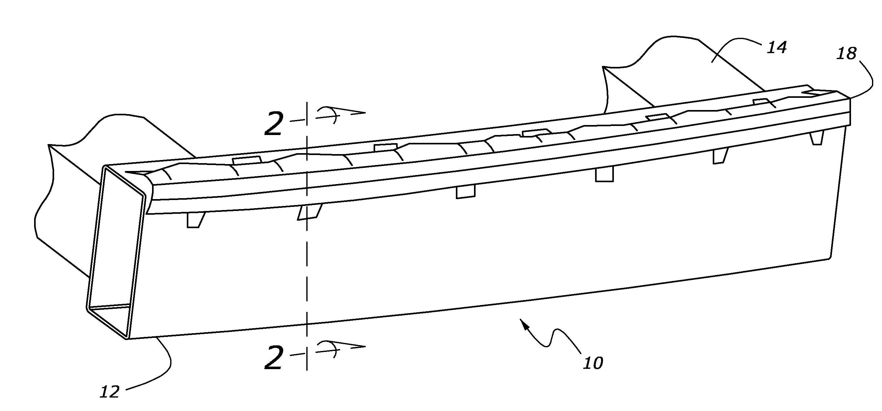
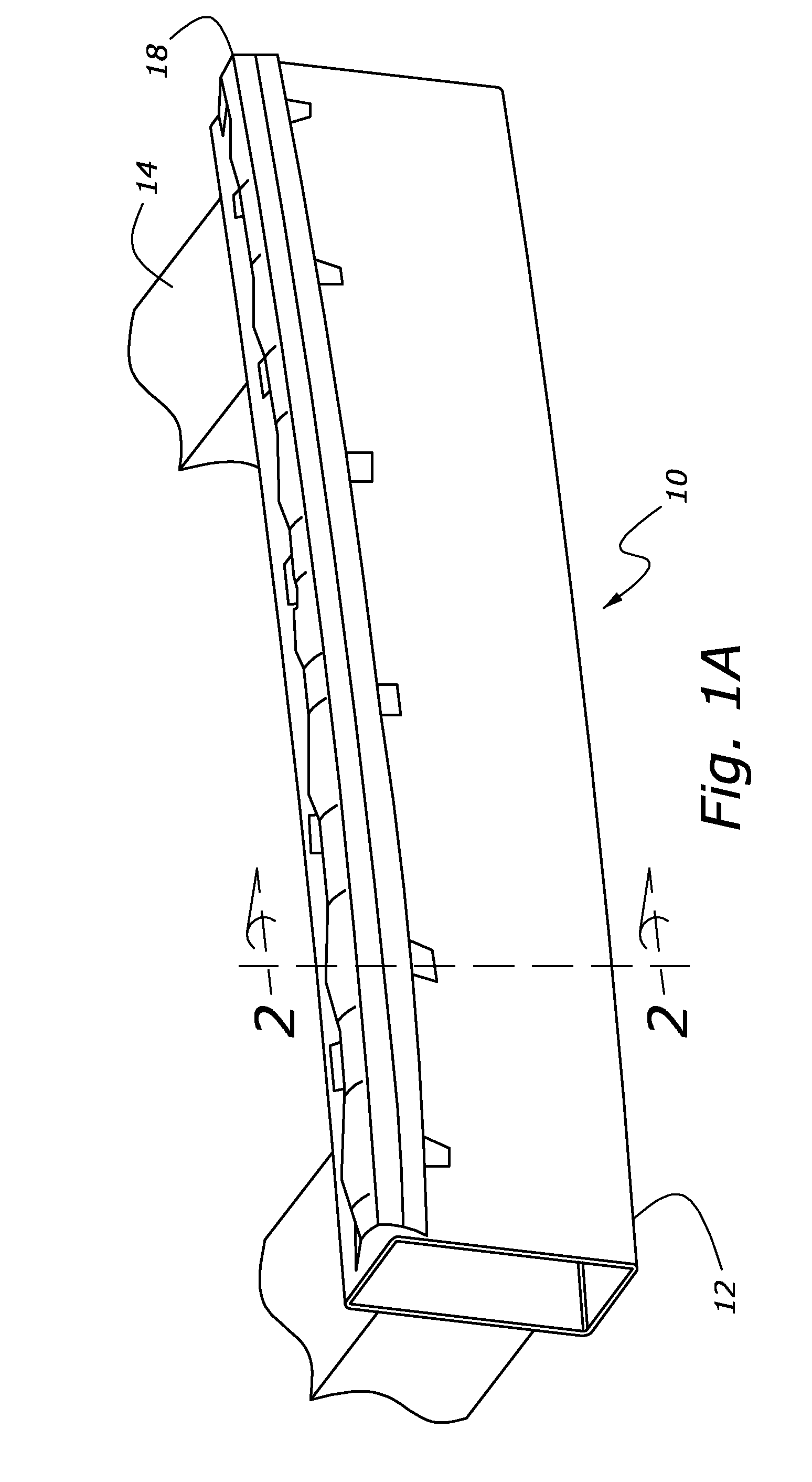
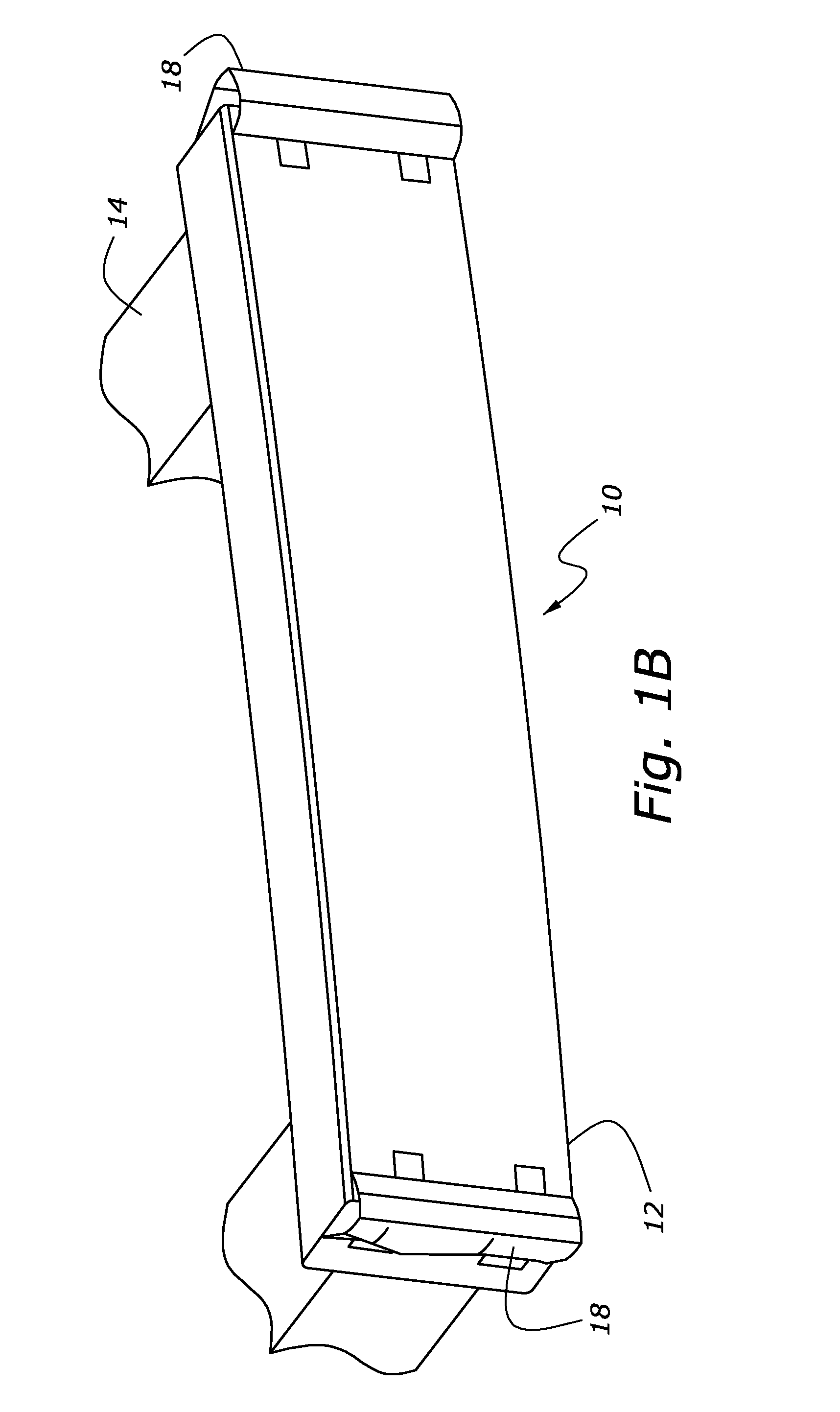
[0042]Referring now to the drawings wherein like reference numerals designate corresponding parts throughout the several views, FIGS. 1A-19 illustrate various embodiments of a bumper system according to the present invention, with the first embodiment being generally designated “bumper system 10”.

[0043]Referring to FIGS. 1A-4, bumper system 10 may generally include a cross beam 12 mounted to frame structure 14 of an automobile (not shown). Cross beam 12 may include an isolator 16 made of foam or other materials known in the art, with isolator 16 being attached to beam 12 in a known manner. A bumper edge guard strip 18 (made of metal for example) may be fixedly mounted or otherwise fixedly engaged (i.e. in a recess (not shown)) along upper and / or lower edges 20, 22 of cross beam 12. Strip 18 may include an upper extension 24 fixedly mounted to or otherwise engaged with upper surface 26 of cross beam 12 by bolt 28, and further include a lower extension 30 fixedly mounted to or otherwi...


PUM


Abstract

An automobile bumper system including an isolator disposed adjacent a cross beam of an automobile frame, and a bumper edge guard strip mounted adjacent upper and/or lower edges of the cross beam. The bumper edge guard strip may include an upper extension fixedly engaged with an upper surface of the cross beam and a lower extension fixedly engaged with a frontal surface of the cross beam, with the upper extension having a length greater than the lower extension for distributing impact energy in a predetermined manner.

Description

BACKGROUND OF INVENTION[0001]a. Field of Invention[0002]The invention relates generally to vehicle structural design, and more particularly, to the structural design of a vehicle bumper system for improved impact deformation and resistance, particularly during bumper over-ride and under-ride conditions.[0003]b. Description of Related Art[0004]As is known in the art, automobile bumper systems are designed to absorb and distribute impact energy in a predetermined manner. While bumpers systems are generally designed to meet at equal vertical impact levels, in the event of bumper over-ride or under-ride (i.e. in the event of a car / truck collision), even a low speed impact can result in excessive vehicle damage. This is because typical bumper systems may include energy absorbers disposed at a height-wise central area of the bumper for providing impact resistance against a bumper presumably disposed at the same height, leaving the upper and lower ends of a bumper susceptible to over-ride ...

Claims


Application Information

Patent Timeline
Patent Type & Authority Applications(United States)
IPC IPC(8): B60R19/04
CPCB60R19/18B60R2019/1873
Inventor FREDERICK, GREGORY S.KUDELKO, CONRAD M.
Owner FORD GLOBAL TECH LLC
Why Eureka
Try Eureka