Data communication apparatus and data communication method

a data communication apparatus and data communication technology, applied in the field of data communication apparatus and data communication method, can solve the problems of increasing the cost of the data communication apparatus, the inability to control the generation of i-frames in any frame period, etc., and achieve the effect of reducing the local generated bias in code amount and smoothing the code amoun

Inactive Publication Date: 2008-12-25
PANASONIC CORP
View PDF12 Cites 9 Cited by
  • Summary
  • Abstract
  • Description
  • Claims
  • Application Information

AI Technical Summary

Benefits of technology

[0032]The data communication apparatus according to the present invention can reduce t

Problems solved by technology

However, the invention disclosed in Japanese Unexamined Patent Application Publication 2004-140651 has two problems.
More specifically, the first problem is that the generation of I-frames cannot be controlled in any frame period.
The second problem is that the method disclosed in

Method used


Image

  • Data communication apparatus and data communication method
  • Data communication apparatus and data communication method
  • Data communication apparatus and data communication method

Examples


first embodiment

[0060]The first embodiment of the data communication apparatus according to the present invention is hereafter described with reference to the drawings.

[0061]Note that the network camera terminal according to the first embodiment is characterized in that the frame control unit generates I-frames corresponding to each stream at the I-frame generation rate described in the generation table which has been held in the frame control unit in advance. In addition, the network camera terminal in the description of the embodiments corresponds to the data communication apparatus in the Claims.

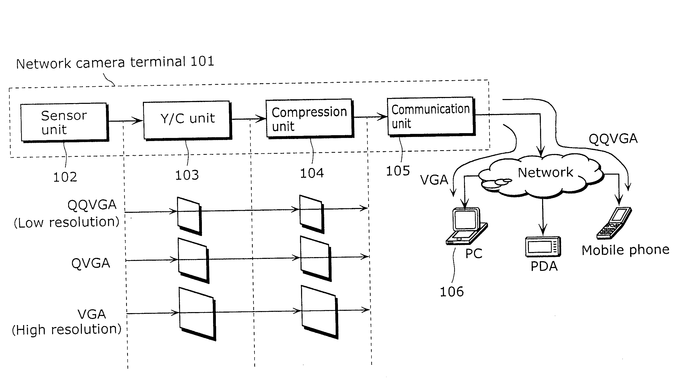
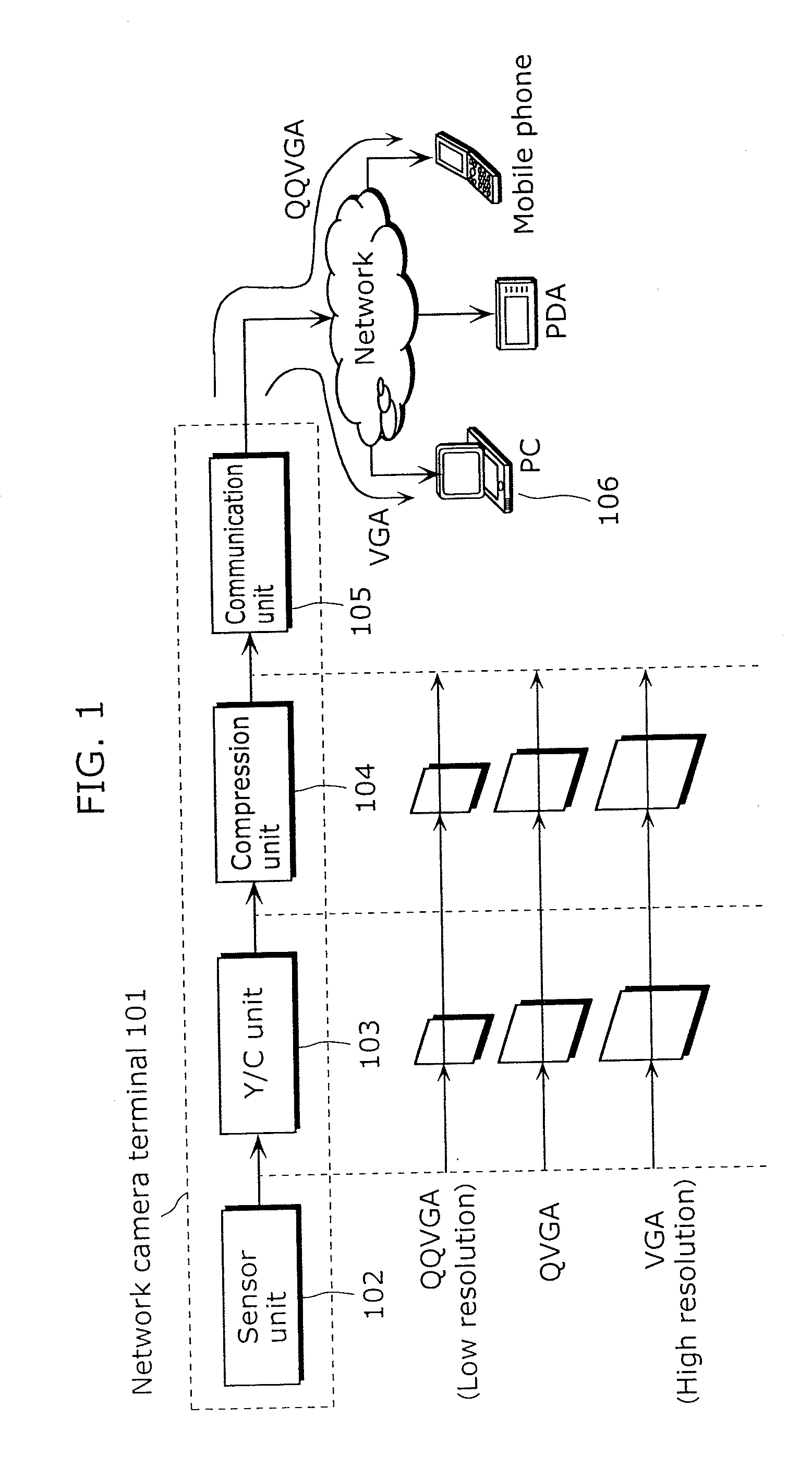
[0062]FIG. 3 is a functional block diagram showing the configuration of the network camera terminal according to the first embodiment.

[0063]The network camera terminal 300 according to the first embodiment includes: the sensor unit 301 to which image information is inputted; the Y / C unit 302 which perform Y / C process to the image loaded from the sensor unit 301; the compression unit 303 which compression...

second embodiment

[0073]The second embodiment according to the present invention is hereafter described with reference to the drawings.

[0074]Note that the network camera terminal according to the second terminal is characterized in that, unlike the network camera terminal in the first embodiment with which the generation rate of I-frame is fixed using the generation table, generation of I-frames in multiple streams are controlled not to overlap each other using decrement counters included in the frame control unit when the generation rates of I-frames vary.

[0075]FIG. 8 is a functional block diagram showing the configuration of the network camera terminal 800 according to the second embodiment.

[0076]The network camera terminal 800 according to the second embodiment includes, in addition to the component in the first embodiment, decrement counters 305a to 305c for counting the number of frames generated in each of the three streams in the frame control unit.[0077]The decrement counter 305a corresponds ...

third embodiment

[0087]The third embodiment according to the present invention is hereafter described with reference to the drawings.

[0088]FIG. 10 is a functional block diagram showing the configuration of the network camera terminal 1000 according to the third embodiment, and the configuration of the network camera terminal 1000 is characterized by, in addition to the components shown in the first embodiment, the bandwidth monitoring unit 1001 that monitors the communication bandwidth of the communication unit 304.

[0089]The operation process of the network camera terminal 1000 according to the third embodiment is hereafter described.

[0090]First, the image information is inputted to the sensor unit 301. The sensor unit 301 digitally converts the image information and transmits the converted information to the Y / C unit 302. The Y / C unit 302 reads the digital data transmitted by the sensor unit 301, and resizes the data after the Y / C process, and transmits the data to the compression unit 303 as the Y...


PUM


Abstract

The present invention provides a data communication apparatus for solving the following problem. When generating coded frames of multiple data streams, in the case where there is a bias in code amount of the generated coded frame, the communication apparatus is instantaneously overloaded, causing packet losses.
The network cameral terminal which is the data communication apparatus includes a sensor unit that takes images or audio information, a compression unit that compression-codes the image or the audio signal and generates coded frames (I-frame, P-frame, B-frame and others), a frame control unit that controls types of the coded frame generated by the compression unit using a generation table held in a generation table holding unit, and a communication unit that transmits the coded frames to multiple communication terminals on the network in parallel.

Description

BACKGROUND OF THE INVENTION[0001](1) Field of the Invention[0002]The present invention relates to a data communication apparatus and data communication method for communicating a compression-coded image or audio signal in real-time using Internet Protocol (IP) conversion processing technology.[0003](2) Description of the Related Art[0004]In recent years, the digital data including images and audio information has been generally transmitted using network lines. These images and audio information are used for various purposes, and many of them are used for monitoring and observation. A network camera terminal is a combination of a camera, an image processor and a network communication apparatus, and the user can browse images and audio in a remote location by accessing the apparatuses installed in a place where the user would like to browse the images and audio.[0005]FIG. 1 is a reference diagram showing an exemplary configuration of the conventional network camera terminal 101. Image...

Claims


Application Information

Patent Timeline
IPC IPC(8): G06F15/16H04L47/2475H04L47/80H04N19/00H04N19/102H04N19/127H04N19/146H04N19/159H04N19/166H04N19/196H04N19/503H04N19/70
CPCH04N7/183H04N21/2187H04N21/23406H04N21/234363H04N21/2381H04N21/2402H04N21/44004H04N21/64322
Inventor YAMAUCHI, SHINICHIROTAKEUCHI, AKIOKOYAMA, TAKAYOSHI
Owner PANASONIC CORP
Why Eureka
Try Eureka