

Command queue loading
a command queue and loading technology, applied in the field of storage systems, can solve the problems of general lack of flexibility in altering the presentation, and achieve the effect of optimizing the flushing performance of dirty data
- Summary
- Abstract
- Description
- Claims
- Application Information
AI Technical Summary
Benefits of technology
Problems solved by technology
Method used
Image

Examples
Embodiment Construction
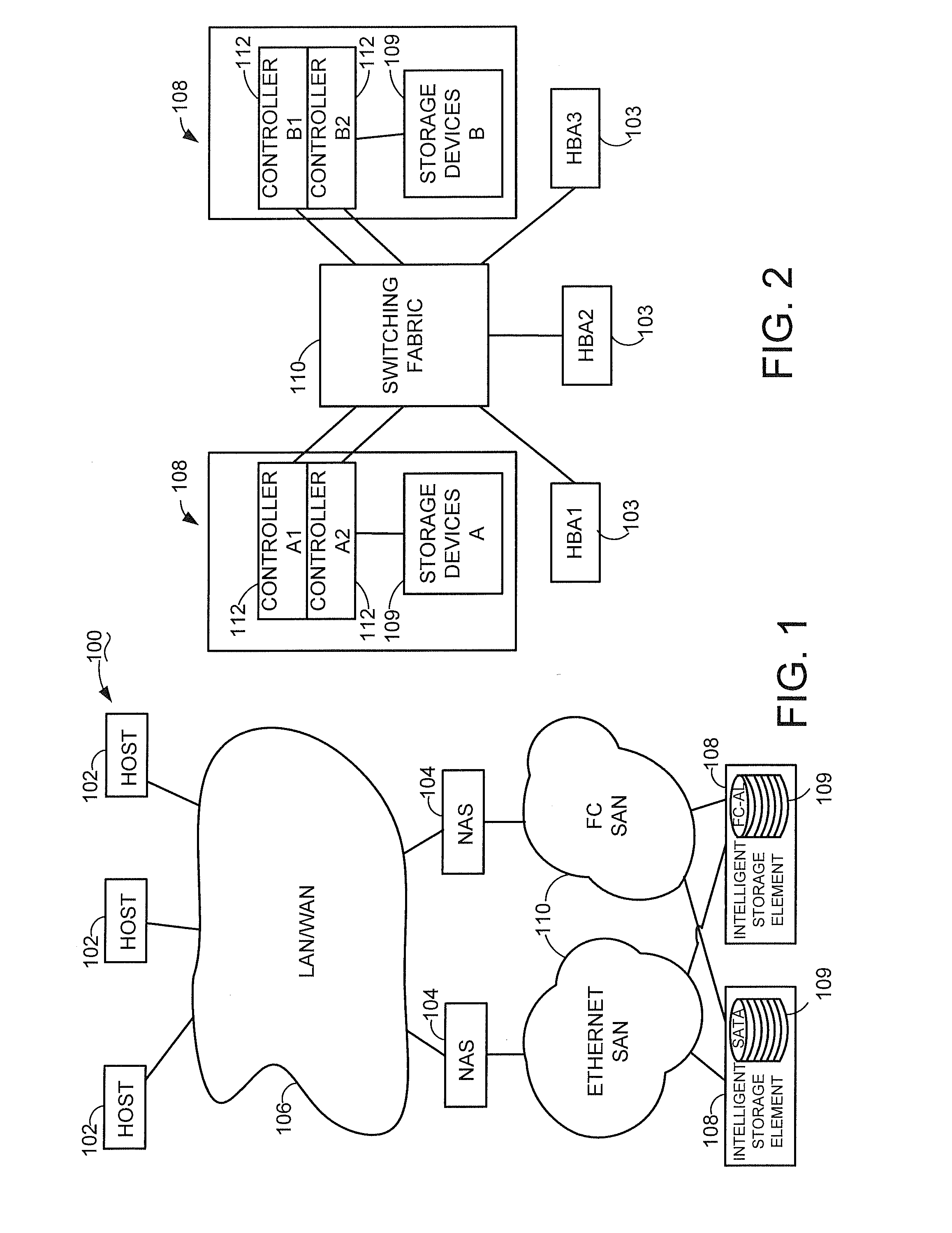
[0018]FIG. 1 is an illustrative computer system 100 incorporating embodiments of the present invention. One or more hosts 102 are networked to one or more network-attached servers 104 via a local area network (LAN) and / or wide area network (WAN) 106. Preferably, the LAN / WAN 106 uses Internet protocol (IP) networking infrastructure for communicating over the World Wide Web. The hosts 102 access applications resident in the servers 104 that routinely need data stored on one or more of a number of intelligent storage elements (ISE) 108. Accordingly, SANs 110 connect the servers 104 to the ISEs 108 for access to the stored data. The ISEs 108 provide a data storage capacity 109 for storing the data over various selected communication protocols such as serial ATA and fibre-channel, with enterprise or desktop class storage medium within.
[0019]FIG. 2 is a simplified diagrammatic view of part of the computer system 100 of FIG. 1. Three host bus adapters (HBA) 103 are depicted interacting wit...
PUM
 Abstract
Description
Claims
Application Information