Linear vibratory conveyor

Inactive Publication Date: 2009-01-08
AFAG HLDG AG
View PDF21 Cites 0 Cited by
  • Summary
  • Abstract
  • Description
  • Claims
  • Application Information

AI Technical Summary

Benefits of technology

[0009]The inventive linear vibratory conveyor or the hybrid conveyor system thus makes it possible to advantageously and selectively integrate different drive units rapidly and simply in terms of assembly, each proceeding from a basic linear vibratory conveyor structure that is always the same, that is, that is somewhat standardized. Thus with nothing further in terms of the employment purpose, the special advantages of each respective drive can be used by the simple integration thereof and with the concurrent simplicity of the conveyor structure in terms of the design of the utility weight and counterweight with respect to connecting the drives. Consequently it is not necessary to produce or keep in the inventory different types of conveyors that are designed with specific drives, but rather a single standardized linear vibratory conveyor is sufficient to be able to integrate the entire spectrum of different drives. The special advantage is also demonstrated for the user in the simple refitting, because if the present linear conveyor is to be used for a different purpose that requires a different drive, the user must merely exchange the drive unit.
[0010]The fastening means are preferably threaded bores into which can be screwed fastening screws that are to be guided through corresponding receiving passages on the respective opposing part. Either threaded bores are provided on the drive unit and receiving passages are provided on the weights or vice versa, “mixed systems” also being possible, of course, i.e. for attaching to the utility mass the utility mass is provided with receiving passages and the drive unit is provided with threaded bores, while for attaching to the counterweight the counterweight has the threaded bore while the drive unit has receiving passages. Ultimately the design here can be as desired, but overall it is useful for facilitating simple and rapid assembly and disassembly.

Problems solved by technology

It is disadvantageous that the structural design of known linear vibratory conveyors that are provided for using electromagnets is different from that when using a piezo-electric actuator, especially with respect to coupling the drive unit to the utility weight and to the counterweight, so that different structural forms result as a function of drive unit.

Method used


Image

  • Linear vibratory conveyor
  • Linear vibratory conveyor
  • Linear vibratory conveyor

Examples


Embodiment Construction

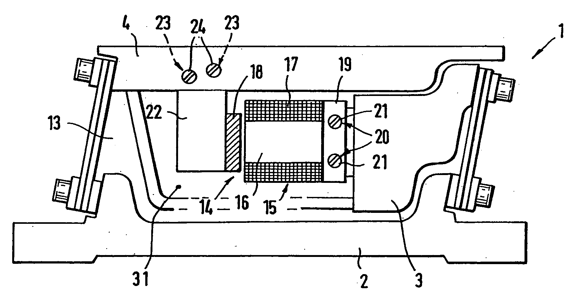
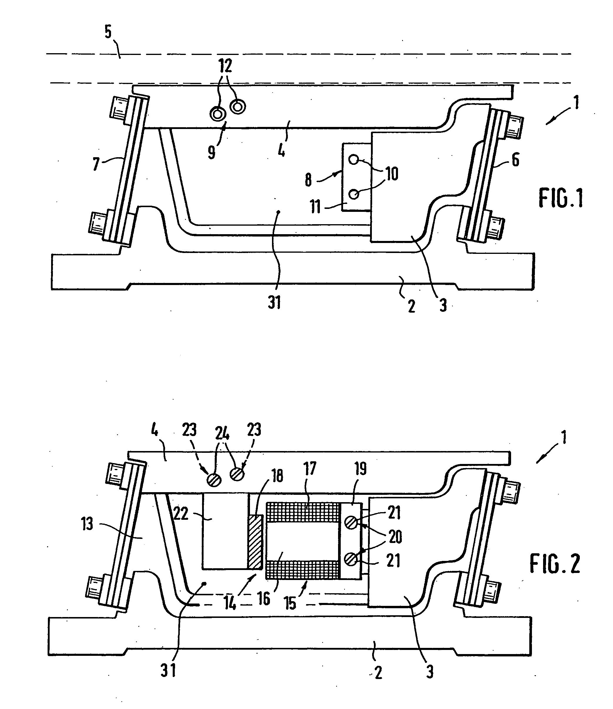
[0015]FIG. 1 depicts the principle for an inventive linear conveyor 1 including a base. plate 2 via which the conveyor is to be connected to a third object, for instance a machine table or frame. Furthermore provided is a counterweight 3 and a utility weight 4 that is separate therefrom and that includes transport rails 5, shown here with broken lines. The counterweight 3 and the utility weight 4 are each connected at both ends to the base plate 2 via spring elements 6, 7, normally leaf spring packages, this making possible vibratingly movable bearing of the counterweight or utility weight 3, 4 relative to the base plate 2 and also to one another. In the figures, only front-most of two spring elements 6, 7 that are in this view one behind the other can be seen, of which one is connected to the counterweight (spring element 6) and the other is connected to the utility weight (spring element 7). The embodiment is such that the two spring elements 6, via which the counterweight 3 is co...


PUM


Abstract

Vibratory linear conveyor that includes a utility weight and a counterweight that can be vibratingly moved in opposing directions via a drive unit, the drive unit being coupled to the utility weight and to the counterweight and being arranged in a receiving chamber beneath the utility weight, whereby a first drive unit including an electromagnet and a second drive unit including a piezo-electric actuator can be exchangeably installed for drive units, identical types of fastening arrangements being provided and positioned identically on each drive unit for connecting to the fastening arrangement arranged on the utility weight and on the counterweight.

Description

BACKGROUND OF THE INVENTION[0001]The invention relates to a linear vibratory conveyor that includes a utility weight and a counterweight that can be vibratingly moved in opposing directions via a drive unit, the drive unit being coupled to the utility weight and to the counterweight and being arranged in a receiving chamber beneath the utility weight.[0002]Such linear vibratory conveyors transport small and very small articles or components that are to be supplied to a working or assembly machine where they are to be processed or installed. The linear vibratory conveyor linearly transports the parts, which are advanced via micro-jumps due to the vibrations generated in the transport rail and along which rail the components are moved. The structure of such a linear vibratory conveyor basically includes a base plate via which the conveyer can be attached to a machine table or the like, and a counterweight and a utility weight, which are both coupled via a drive unit and using the latt...

Claims


Application Information

Patent Timeline
IPC IPC(8): B65G27/24
CPCB65G27/30B65G27/24
Inventor BOEGER, CHRISTIANBOTT, KLAUSEDBAUER, FRANZ
Owner AFAG HLDG AG
Why Eureka
Try Eureka