Imaging lens, camera module, and imaging apparatus

a technology of imaging apparatus and camera module, which is applied in the direction of optics, instruments, optics, etc., can solve the problems of insufficient image forming performance and compactness, mainly required cost performance and compactness, and achieve high imaging performance, reduce the size of the whole system, and high resolution

Active Publication Date: 2009-01-15
TIANJIN OFILM OPTO ELECTRONICS CO LTD
View PDF9 Cites 31 Cited by
  • Summary
  • Abstract
  • Description
  • Claims
  • Application Information

AI Technical Summary

Benefits of technology

[0008]An object of an illustrative, non-limiting embodiment of the invention is to provide: an imaging lens, which can decrease size of the whole system and achieve high imagin...

Problems solved by technology

Especially, with respect to the imaging lens for a mobile camera module, there have been mainly required cost performance and compactness.
However, ...

Method used


Image

  • Imaging lens, camera module, and imaging apparatus
  • Imaging lens, camera module, and imaging apparatus
  • Imaging lens, camera module, and imaging apparatus

Examples


examples

[0087]Hereinafter, specific numerical examples of the imaging lens according to the embodiment will be described. In the following explanation, first to eighth numerical examples will be collectively described.

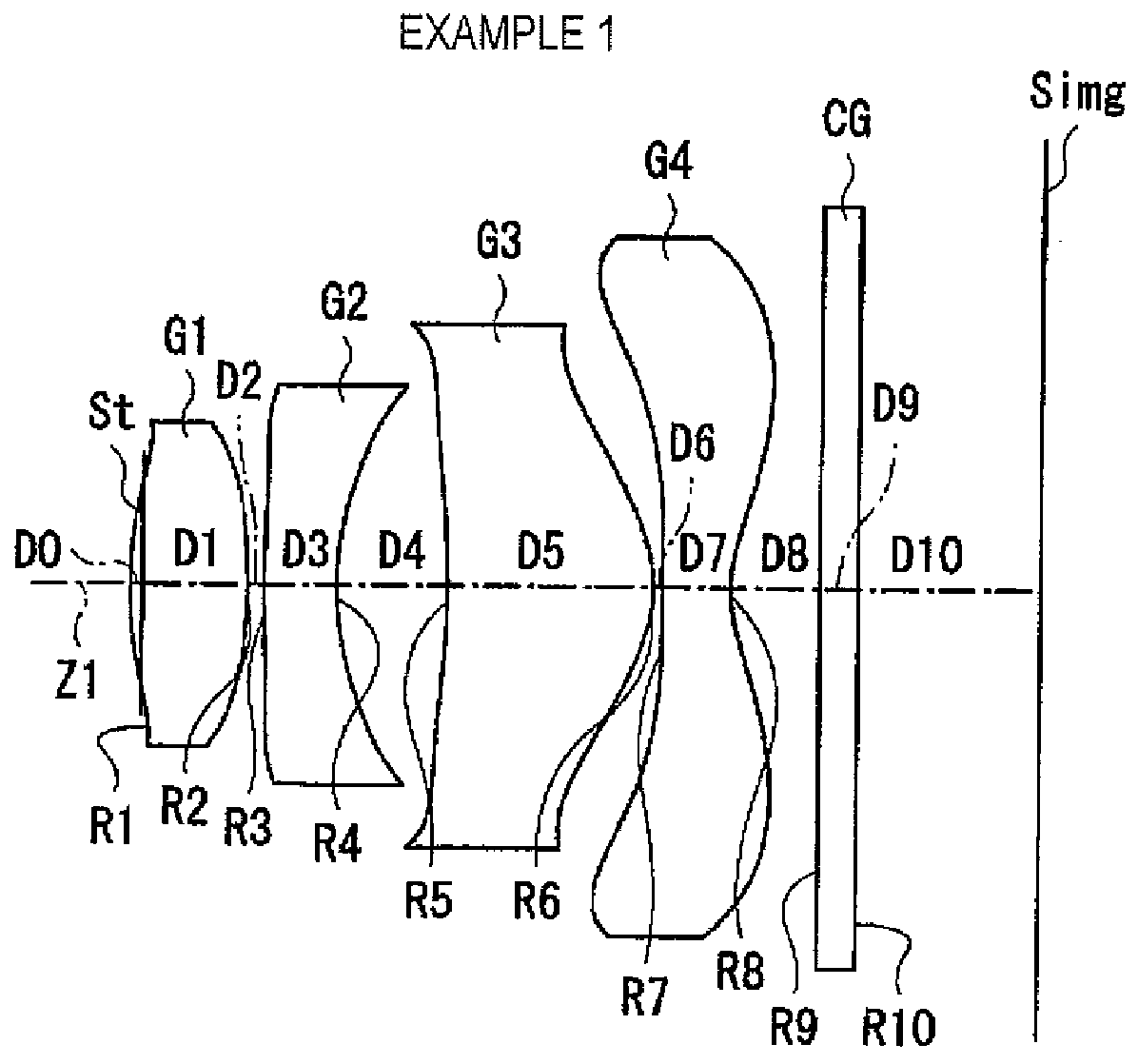
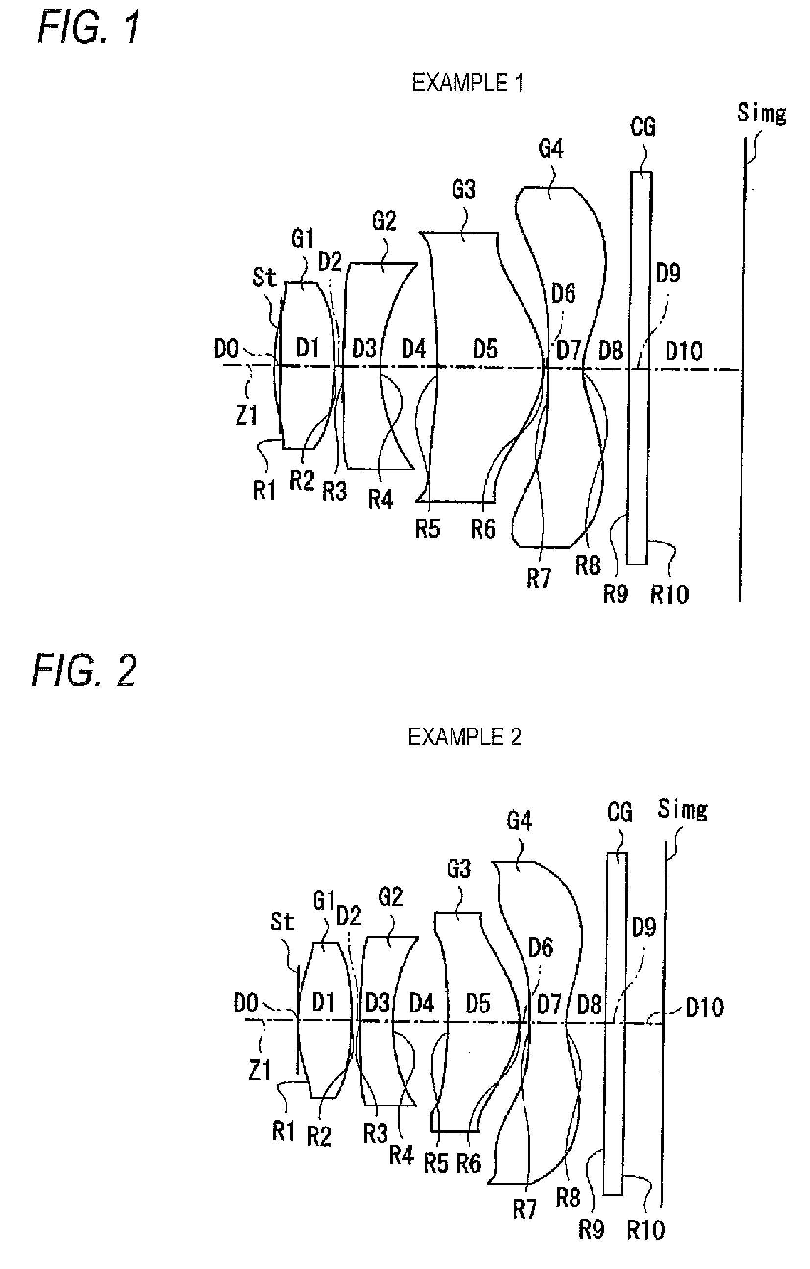
[0088]FIGS. 9A and 9B show specific lens data corresponding to the configuration of the imaging lens shown in FIG. 1. Particularly, FIG. 9A shows basic lens data, FIG. 9B shows aspherical data. In the column of the surface number Si in the lens data shown in FIG. 9A, the number i represents the sequential number of i-th surface that sequentially increases as it gets closer to the image side when a surface of a component closest to the object side is regarded as a first surface (an aperture diaphragm St is a zeroth element), with regard to the imaging lens according to Example 1. In the column of the radius of curvature Ri, there are shown values (mm) of the radius of curvature of i-th surface from the object side to correspond to the reference sign Ri in FIG. 1. Likewise, in t...


PUM


Abstract

An imaging lens is provided and includes: in order from an object side of the imaging lens, a first lens having a positive power; a second lens having a negative power; a third lens having a positive power and having a convex surface on an image side thereof; and a fourth lens having a negative power and having a concave surface or a flat surface on the object side and in a vicinity of an optical axis thereof, and the imaging lens satisfies conditional expression:
0.28<|f4/f|<0.60   (1)
where f is a focal length of the imaging lens, and f4 is a focal length of the fourth lens.

Description

[0001]This application is based on and claims priority under 35 U.S.C §119 from Japanese Patent Application No. 2007-181016, filed on Jul. 10, 2007, the entire disclosure of which is herein incorporated by reference.BACKGROUND OF THE INVENTION[0002]1. Field of the Invention[0003]The present invention relates to an imaging lens that forms an optical image of a subject on an imaging device such as a CCD (Charge Coupled Device) or a CMOS (Complementary Metal Oxide Semiconductor), a camera module that converts the optical image formed by the imaging lens into an imaging signal, and an imaging apparatus such as a cellular phone and a portable information terminal (PDA: Personal Digital Assistance) equipped with a camera or a digital still camera that performs photographing with the imaging lens mounted therein.[0004]2. Description of Related Art[0005]In recent years, as personal computers have become popular in homes, digital still cameras capable of transferring image information about ...

Claims


Application Information

Patent Timeline
IPC IPC(8): G02B9/34
CPCG02B13/004G02B9/34G02B13/18G02B1/02
Inventor TANIYAMA, MINORU
Owner TIANJIN OFILM OPTO ELECTRONICS CO LTD
Why Eureka
Try Eureka