Pump assembly

a technology of pump assembly and assembly plate, which is applied in the direction of piston pumps, pump components, non-positive displacement fluid engines, etc., can solve the problems of increased total friction of the pump assembly, increased power loss, and increased assembly effort, so as to improve the connection

Active Publication Date: 2009-02-05
GRUNDFOS MANAGEMENT AS
View PDF10 Cites 5 Cited by
  • Summary
  • Abstract
  • Description
  • Claims
  • Application Information

AI Technical Summary

Benefits of technology

[0031]In order to further improve the connection between the collar and the non-metallic material, a surface of the collar is structured or roughened, preferably before the connection to the non-metallic material. This may be effected, for example, by laser radiation, wherein small recesses or crater-like raised parts are incorporated into the surface of the collar by a laser beam, in which the non-metallic material, for example plastic, flows on casting, and thus creates a firm connection to the collar, on the one hand via a larger surface and on the other hand via a positive fit.

Problems solved by technology

This, on the one hand, leads to a more complicated construction of the pump assembly, whereby the assembly requires more effort.
On the other hand, the total friction of the pump assembly is also increased, whereby the power loss is increased.

Method used


Image

  • Pump assembly
  • Pump assembly
  • Pump assembly

Examples


Embodiment Construction

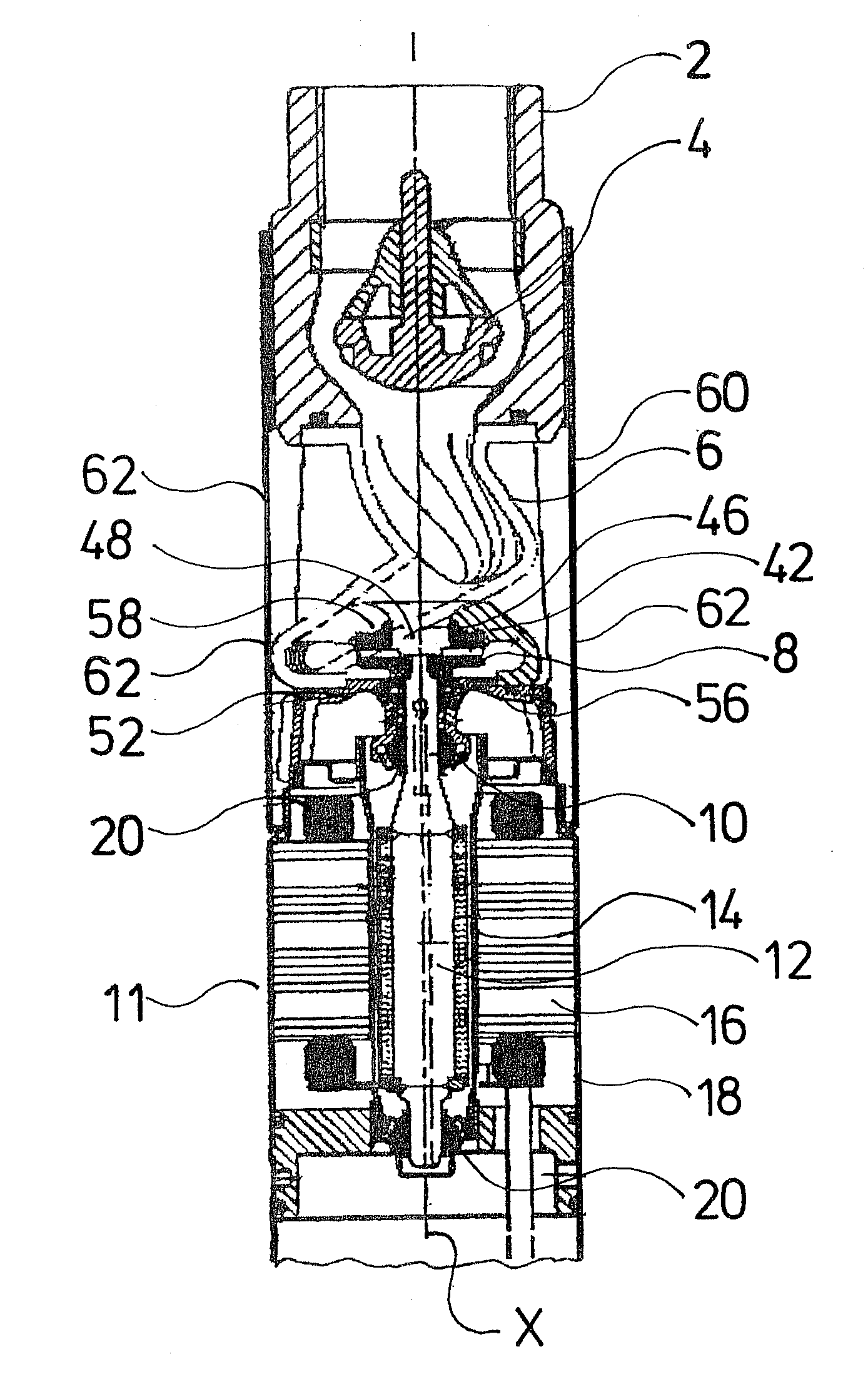
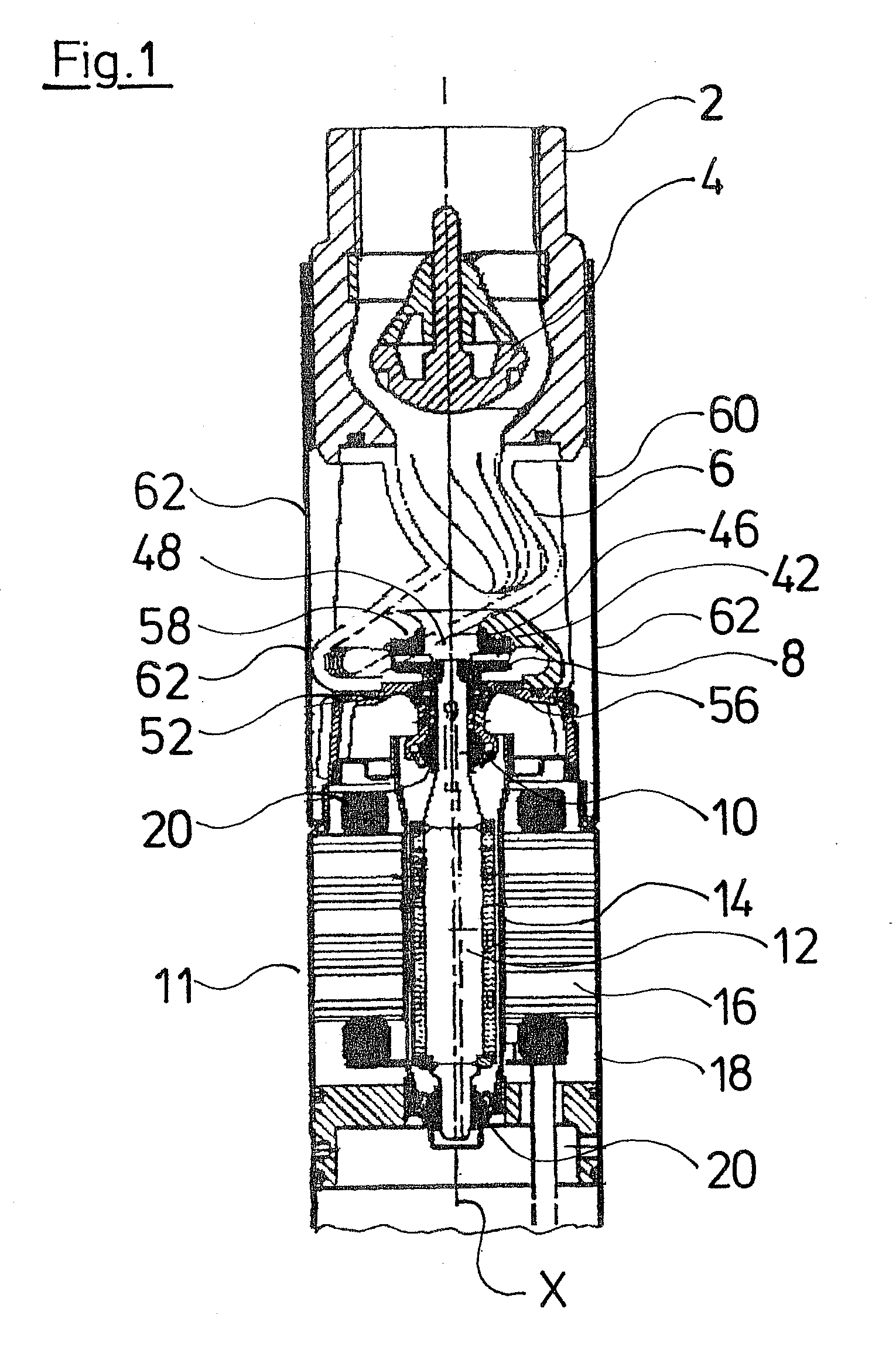
[0039]FIG. 1 shows a sectional view of the upper end of a submersible pump. The lower end, in which the electronics for the control and regulation of the pump are attached, is not shown in the Figure. The pump assembly at its upper end comprises a connection stub 2 with a return valve 4 arranged therein. A spiral housing 6 which surrounds the impeller 8, connects upstream to the connection stub 2 in the inside of the pump assembly. The impeller 8 is arranged at the axial end of the single-piece rotor shaft 10 of the electric motor 11 or its permanent magnet rotor 12. The impeller 8 is firmly fixed on the rotor shaft 10, in particular is also firmly connected in the axial direction X. The permanent magnet rotor 12 runs inside of a can 14 which is annularly surrounded on its outer periphery by the stator 16. The stator 16 is designed in a known manner as a lamination bundle with coil windings. The stator 16 is hermetically encapsulated as a whole in a stator housing 18. The rotor shaf...


PUM


Abstract

A pump unit is provided having a wet-running electric motor, wherein a rotor of the pump unit can be driven by the electric motor at a maximum speed of greater than 20,000 rev/min, and the rotor is sealed off axially in the region of a suction port.

Description

CROSS-REFERENCE TO RELATED APPLICATIONS[0001]This application is a Section 371 of International Application No. PCT / EP2006 / 009113, filed Sep. 20, 2006, which was published on Mar. 29, 2007, under International Publication No. WO 2007 / 033817 A1 and the disclosure of which is incorporated herein by reference.BACKGROUND OF THE INVENTION[0002]The invention relates to a pump assembly with a wet-running electric motor.[0003]Pump assemblies with wet-running electric motors are, for example, applied as submersible pump assemblies or heating circulation pump assemblies. Particularly with submersible pump assemblies, a high delivery capacity with a compact construction and low energy consumption are desirable. In order to achieve greater delivery capacities, usually several stages are provided in submersible pump assembles. This, on the one hand, leads to a more complicated construction of the pump assembly, whereby the assembly requires more effort. On the other hand, the total friction of t...

Claims


Application Information

Patent Timeline
Patent Type & Authority Applications(United States)
IPC IPC(8): F04D13/08
CPCF04D29/041F04D13/086F04D13/0633F04D13/0626F04D29/0413
Inventor GRANN, HELGERASMUSSEN, CHRISTIAN
Owner GRUNDFOS MANAGEMENT AS
Why Eureka
Try Eureka