This helps you quickly interpret patents by identifying the three key elements:
Problems solved by technology
Method used
Benefits of technology
[0021]Advantages of the invention are: as the toaster is started, the sliders move downwards, the bread-elevating mechanism forces the extension spring to pull the steel meshes along the grooves in parallel and to uniformly fix the steel meshes on the surface of the breads, and
Problems solved by technology
However, the heating chamber is comparatively small and only fit for heating thin breads.
If the heating chamber is enlarged, as thin breads are disposed in the bread-receiving slot, only an upper portion of the stee
Method used
Image
Click on the blue label to locate the original text in one second.
Reading with bidirectional positioning of images and text.
Examples
Example
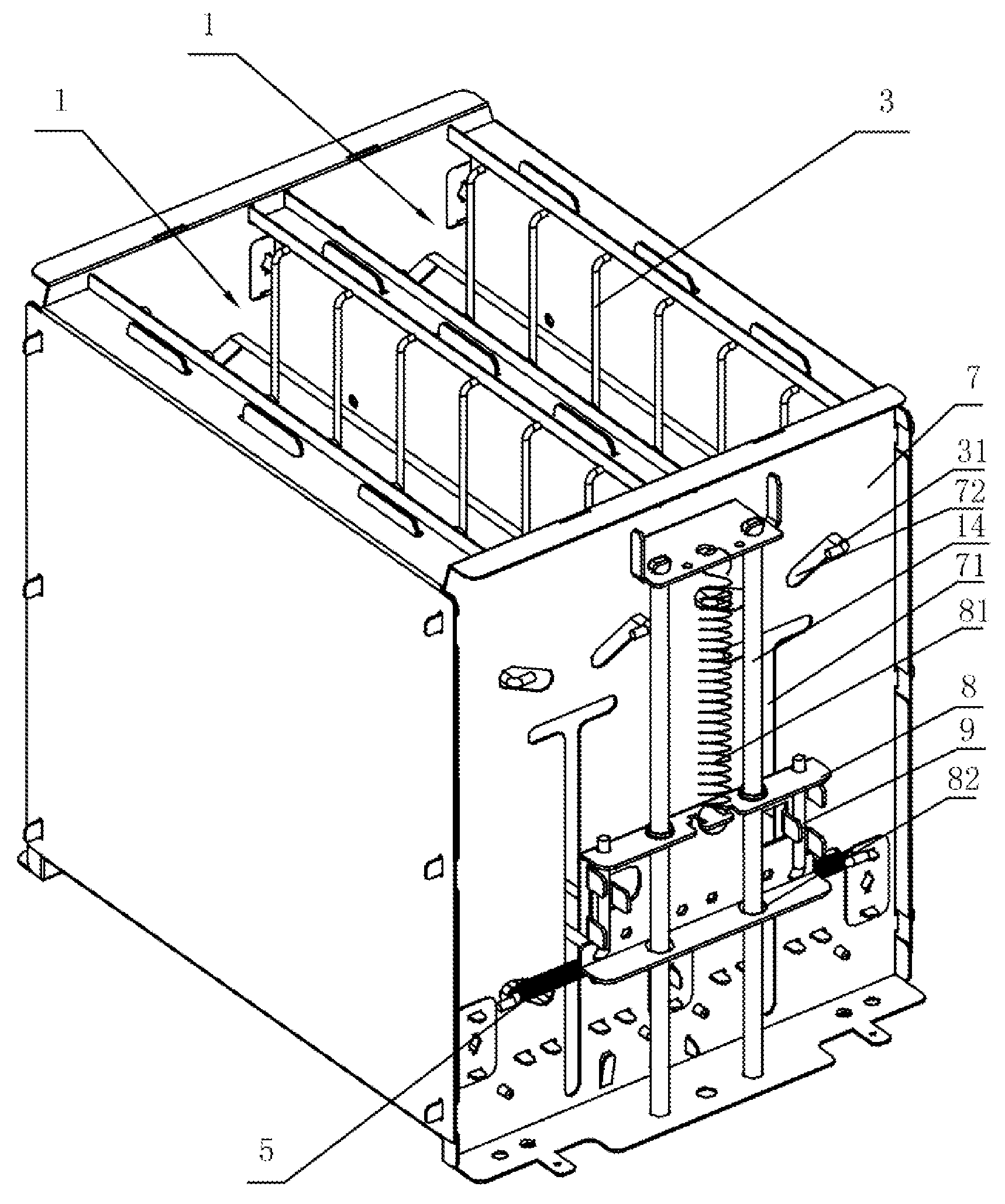
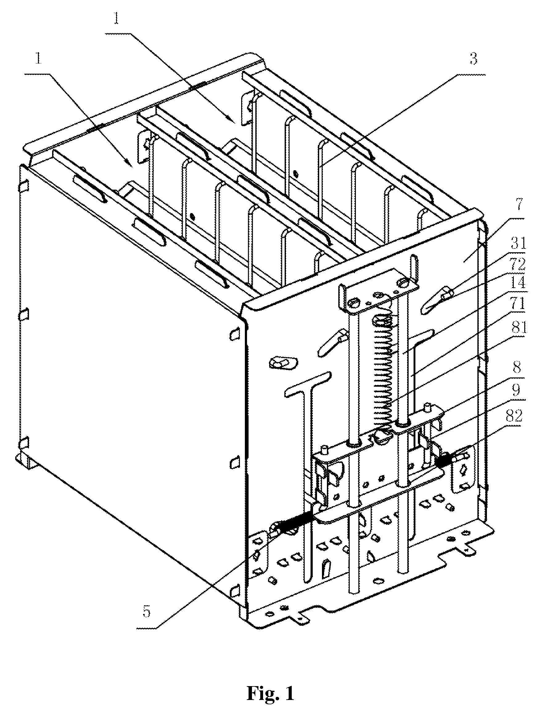
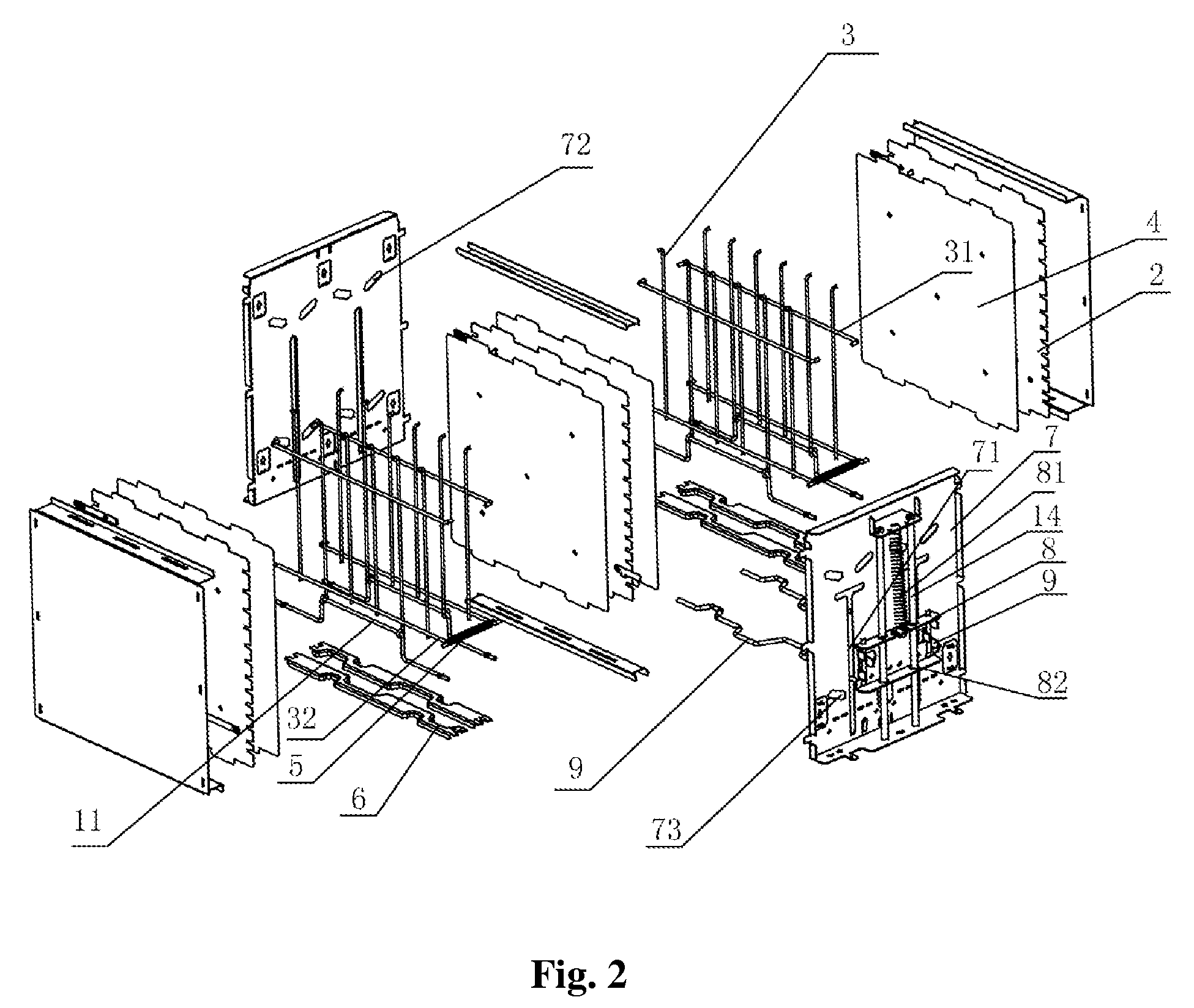
[0033]As shown in FIGS. 1-4, a toaster chassis of a first embodiment of the invention comprises a pair of heating chambers 1, a plurality of mica heating units 2, a pair of steel meshes 3, a separator 4, a bread-receiving slot 6, a pair of supporting plates 7, a slider 8 and a bread-elevating mechanism 9. The steel meshes 3 are disposed in the heating chamber 1, the separator 4 is disposed between the mica heating unit 2 and the steel mesh 3, the bread-receiving slot 6 is disposed below the heating chamber 1, the supporting plate 7 is disposed on both ends of the heating chamber 1, and the slider 8 is connected to an external button (not shown) and disposed on one side of said supporting plate 7.
[0034]A pair of crank shaft 11 corresponding to the steel meshes 3 are disposed below the heating chamber 1, and each comprises a pair of axle bars 111 disposed on both ends thereof and a curved bar 112 disposed in the center thereof. The axle bar 111 is connected to the supporting plate 7.
[...
Example
[0040]As shown in FIGS. 5-8, a toaster chassis of a second embodiment of the invention comprises a pair of heating chambers 1, a plurality of mica heating units 2, a pair of steel meshes 3, a separator 4, a bread-receiving slot 6, a pair of supporting plates 7, a slider 8, a bread-elevating mechanism 9 and a slingshot 10. The steel meshes 3 are disposed in the heating chamber 1, the separator 4 is disposed between the mica heating unit 2 and the steel mesh 3, the bread-receiving slot 6 is disposed below the heating chamber 1, the supporting plate 7 is disposed on both ends of the heating chamber 1, the slider 8 is connected to an external button (not shown) and disposed on one side of said supporting plate 7, and the slingshot 10 is disposed in the center of the supporting plate 7, and comprises a pair of elastic supporting bars.
[0041]A pair of crank shafts 11 corresponding to the steel meshes 3 are disposed below the heating chamber 1, and each comprises a pair of axle bars 111 dis...
Example
[0048]In a third embodiment of the invention, all elements are the same as those in the first embodiment, except for a pattern template 15 disposed on the steel mesh 3.
PUM
Abstract
Provided is a toaster chassis, comprising at least one heating chamber, a pair of steel meshes, a bread-elevating mechanism, a pair of supporting plates, a pair of grooves, a pair of sliding rods and an extension spring; wherein the supporting plates are disposed on both ends of the heating chamber, the grooves are disposed on the supporting plate, the sliding rods are disposed on the steel mesh, pass through the supporting plate and abut against the grooves, the extension spring is disposed below the bread-elevating mechanism, and both ends of the extension spring are connected to the sliding rods. The invention is applicable for breads with different thickness and capable of ensuring uniformity of heat and consistency of colors on both sides and the upper and lower portion of each thereof.
Description
CROSS-REFERENCE TO RELATED APPLICATIONS[0001]This application claims priority benefits to Chinese Patent Application No. 200710071269.9 filed on Sep. 10, 2007. The contents of all of the aforementioned specifications are incorporated herein by reference.BACKGROUND OF THE INVENTION[0002]1. Field of the Invention[0003]The invention relates to a toaster, and more particularly to a toaster chassis.[0004]2. Description of the Related Art[0005]Conventionally, a toaster comprises a chassis and a control circuit, and the chassis comprises at least one heating chamber, a pair of steel meshes, a pair of bread-receiving slots, a pair of supporting plates, a plurality of mica heating units and a pattern template. During operation, after breads are put into the bread-receiving slots and the toaster is started, the bread-receiving slots force the breads to move downwards, the steel meshes and the mica heating units respectively fix and heat the breads, and the pattern template presents different ...
Claims
Application Information
Patent Timeline
Application Date:The date an application was filed.
Publication Date:The date a patent or application was officially published.
First Publication Date:The earliest publication date of a patent with the same application number.
Issue Date:Publication date of the patent grant document.
PCT Entry Date:The Entry date of PCT National Phase.
Estimated Expiry Date:The statutory expiry date of a patent right according to the Patent Law, and it is the longest term of protection that the patent right can achieve without the termination of the patent right due to other reasons(Term extension factor has been taken into account ).
Invalid Date:Actual expiry date is based on effective date or publication date of legal transaction data of invalid patent.