Stereoscopic image display apparatus and stereoscopic image display method

a stereoscopic image and display apparatus technology, applied in the field of stereoscopic image display apparatus and stereoscopic image display method, can solve the problems of narrow zone, difficult to realize full color moving pictures, narrow viewing point range from which stereoscopic viewing can be conducted, etc., to prevent luminance differences and large number of parallaxes

Inactive Publication Date: 2009-03-26
KK TOSHIBA
View PDF6 Cites 19 Cited by
  • Summary
  • Abstract
  • Description
  • Claims
  • Application Information

AI Technical Summary

Benefits of technology

[0010]The present invention has been made in view of these circumstances, and an object of thereof is to provide a stereoscopic image display apparatus and a stereoscopic image display method capab

Problems solved by technology

As for a scheme utilizing the principle of holography among stereoscopic moving picture display apparatuses of this type, realization of full color moving pictures is difficult.
On the other hand, the binocular and multiview schemes have a problem that the range of the viewing point position from which stereoscopic viewing can be conducted, i.e., the viewing zone is narrow and it is hard to view.
In such a direct view type stereoscopic image display apparatus using a slit array or a lenticular sheet, the luminance becomes high as the parallax position approaches the center because of viewing angle characteristics of a display

Method used


Image

  • Stereoscopic image display apparatus and stereoscopic image display method
  • Stereoscopic image display apparatus and stereoscopic image display method
  • Stereoscopic image display apparatus and stereoscopic image display method

Examples


Embodiment Construction

[0026]Hereafter, embodiments of the present invention will be described with reference to the drawings.

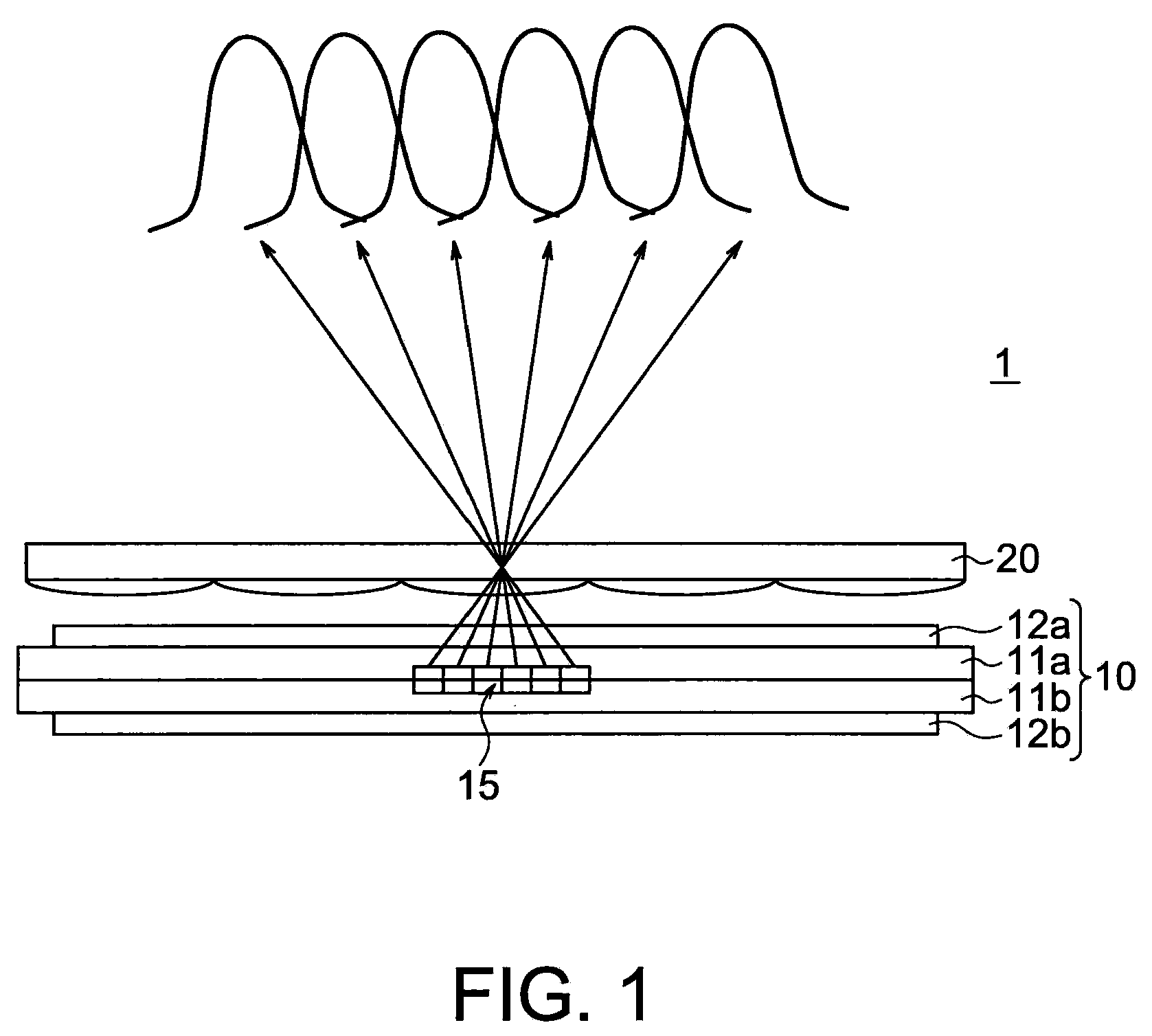
[0027]A stereoscopic image display apparatus according to an embodiment of the present invention is shown in FIG. 1. FIG. 1 is a lateral-direction section view of a stereoscopic image display apparatus 1 according to the present embodiment. A display unit 10 is a liquid crystal panel. There is a pixel plane between two glass substrates 11a and 11b. Sheet polarizers 12a and 12b are provided outside the glass substrates 11a and 11b. Each of pixels on the liquid crystal panel 10 is divided into sub-pixels respectively having three color components (for example, color components of R (red), G (green) and B (blue)) in the lateral direction. An optical plate 20 is a lenticular sheet. A pixel group corresponding to one lens of the lenticular sheet 20 is one elemental image 15. In FIG. 1, the elemental image 15 is a row of six sub-pixels. Light rays from the elemental image 15 are emitted ...


PUM


Abstract

It is made possible to provide a stereoscopic image display apparatus capable of preventing a luminance difference from being caused between left and right eyes irrespective of the observation position even if the viewing zone is wide and the number of parallaxes is large. A stereoscopic image display apparatus includes: a display unit including pixels arranged in a matrix form in a longitudinal direction and a lateral direction; an optical plate installed so as to be opposed to the display unit and having linear optical openings prolonged in a longitudinal direction and arranged in a lateral direction; and a luminance compensation processing unit which, for each of elemental images associated with the optical openings, sets a brightness of an image displayed on a pixel located in a center of the elemental image smaller than a brightness of an image displayed on a pixel located in each of boundaries of the elemental image.

Description

CROSS-REFERENCE TO RELATED APPLICATION[0001]This application is based upon and claims the benefit of priority from prior Japanese Patent Application No. 2007-246984 filed on Sep. 25, 2007 in Japan, the entire contents of which are incorporated herein by reference.BACKGROUND OF THE INVENTION[0002]1. Field of the Invention[0003]The present invention relates to a stereoscopic image display apparatus and a stereoscopic image display method.[0004]2. Related Art[0005]As for a stereoscopic image display apparatus capable of displaying a moving picture, i.e., the so-called three-dimensional display, various schemes are known. In recent years, demand especially for a scheme that uses a flat panel type and that does not need dedicated glasses is increasing. As for a scheme utilizing the principle of holography among stereoscopic moving picture display apparatuses of this type, realization of full color moving pictures is difficult. However, a scheme of installing an optical plate, which contr...

Claims


Application Information

Patent Timeline
IPC IPC(8): H04N13/00G03B35/00
CPCG03B35/00
Inventor SAISHU, TATSUOTAIRA, KAZUKITAKAGI, AYAKOKASHIWAGI, MASAKO
Owner KK TOSHIBA
Why Eureka
Try Eureka