Display device
a display device and liquid crystal technology, applied in non-linear optics, instruments, optics, etc., can solve the problems of frame-like luminance difference generation and disturbance of liquid crystal orientation, and achieve the effect of preventing the generation of frame-like luminance differen
- Summary
- Abstract
- Description
- Claims
- Application Information
AI Technical Summary
Benefits of technology
Problems solved by technology
Method used
Image
Examples
embodiment 1
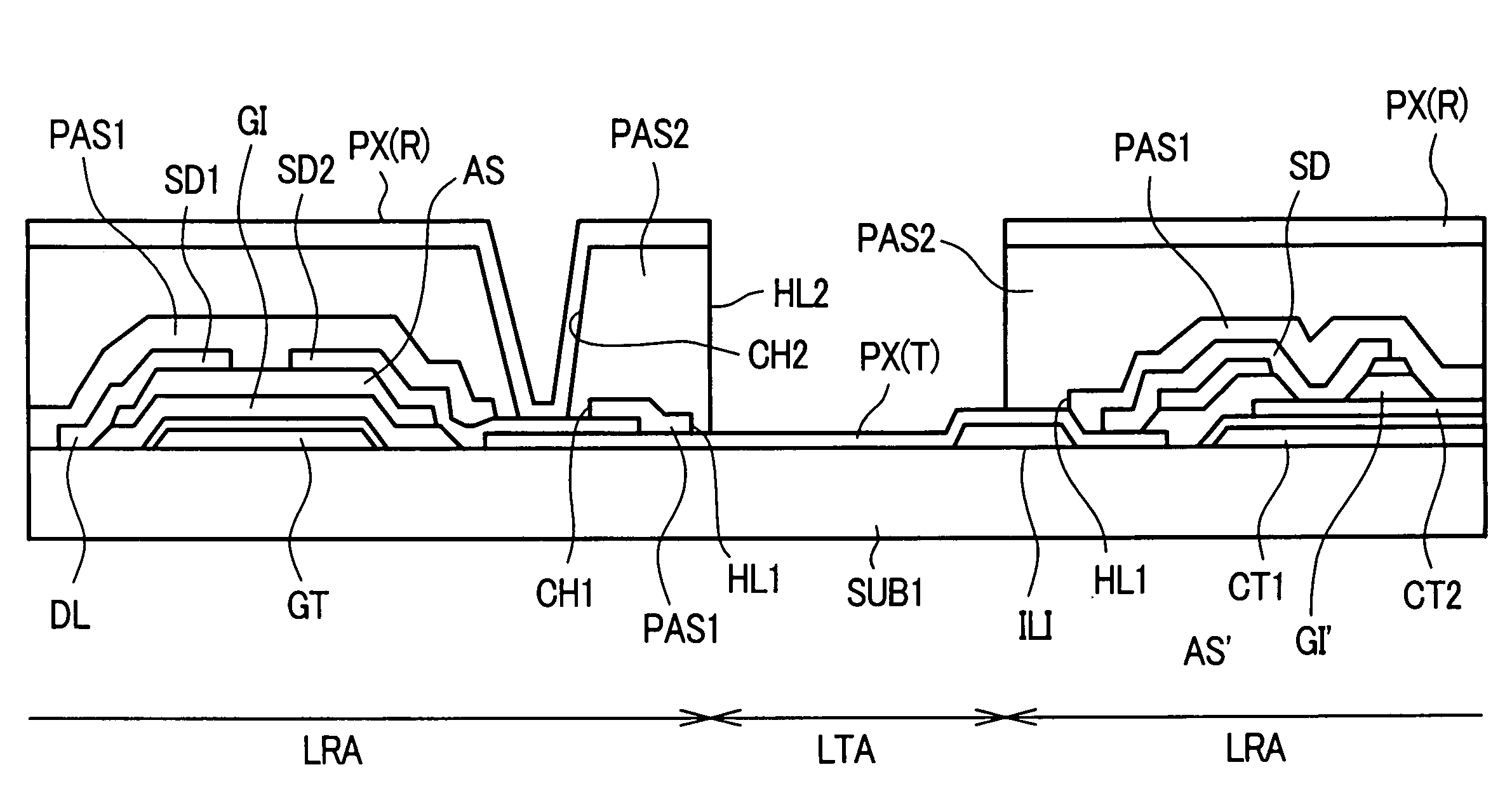
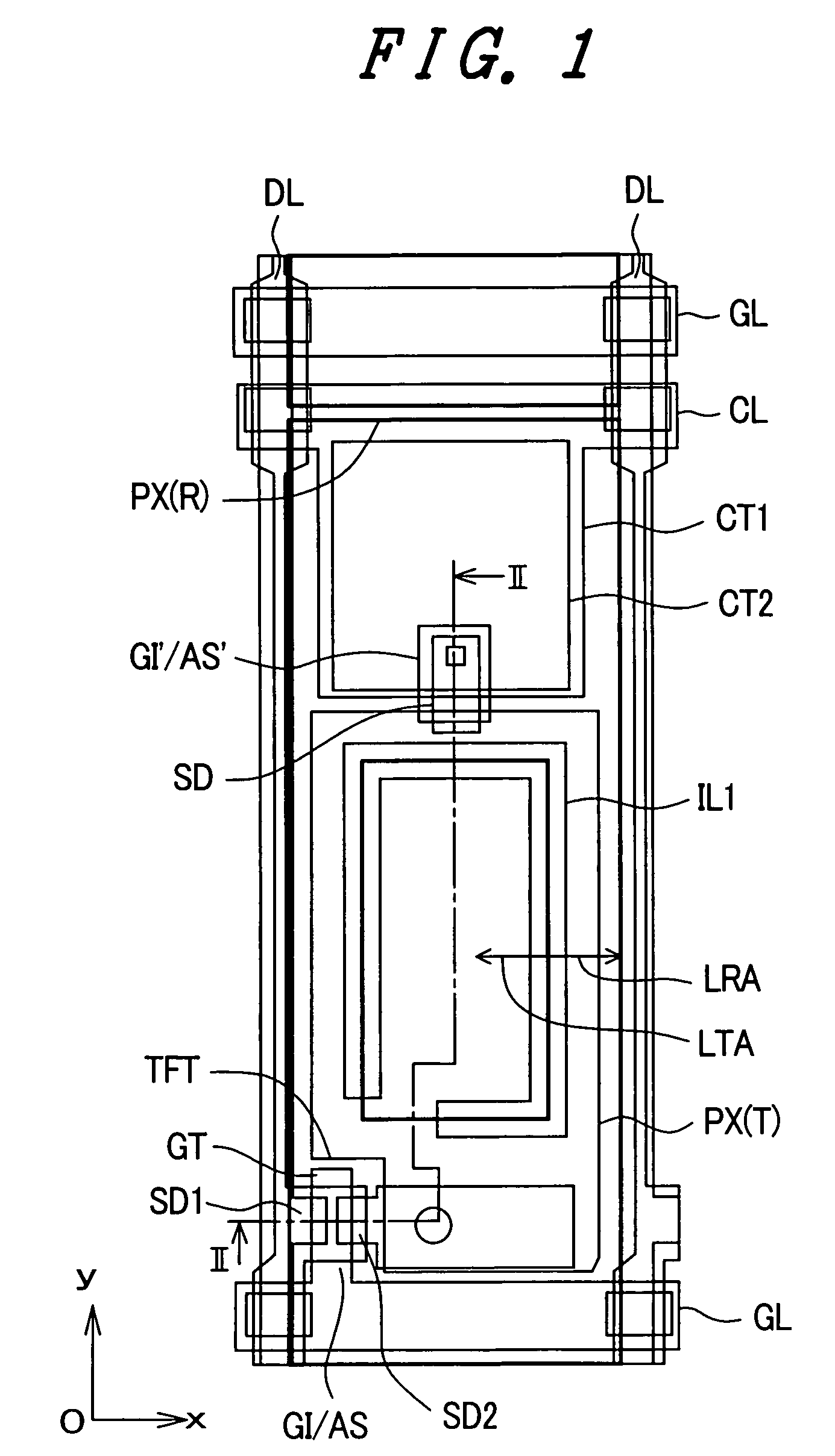
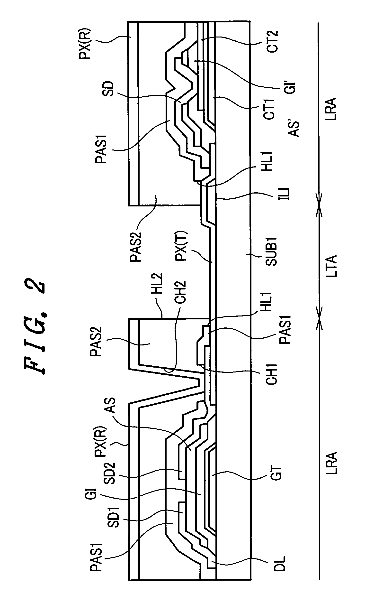
[0028]FIG. 1 is a plan view showing one embodiment of the constitution of a pixel of a liquid crystal display device according to the present invention. Further, FIG. 2 is a cross-sectional view taken along a line II-II in FIG. 1.
[0029]Pixels as seen in these drawings are formed within regions which are defined by gate signal lines GL, which extend in the x direction and are juxtaposed in the y direction, and drain signal lines DL, which extend in the y direction and are juxtaposed in the x direction (pixel regions).
[0030]First, the above-mentioned gate signal lines GL are formed on the liquid-crystal-side surface of the transparent substrate SUB1. The gate signal line GL has a portion which is extended slightly to the pixel region side and this extended portion forms a gate electrode GT of a thin film transistor TFT, as will be explained in more detail later. This gate signal line GL and the gate electrode GT are made of, for example, aluminum (Al) or an alloy thereof and an anodiz...
embodiment 2
[0063]FIG. 4 is a plan view showing another embodiment of the pixel of the liquid crystal display device according to the present invention, similar tot hat of FIG. 1.
[0064]The constitution which makes this embodiment different from the embodiment shown in FIG. 1 lies in the fact that the light shielding layer ILI is formed not only in the vicinity of the thin film transistor TFT within the boundary portion between the light transmissive region LTA and the light reflective region LRA, but also in other portions within such a boundary portion, for example, in the vicinity of the capacitive element Cstg.
[0065]This constitution is provided for eliminating, with high probability, the drawback that occurs when the pixel electrode PX (T) is formed by extending it over the light shielding layer ILI, such that it is broken at the stepped portion of the light shielding layer ILI.
embodiment 3
[0066]FIG. 5 is a plan view showing another embodiment of a pixel of the liquid crystal display device according to the present invention and it shows an arrangement similar to that of FIG. 1.
[0067]The constitution which makes this embodiment different from the embodiment shown in FIG. 1 lies in the fact that the light shielding layer ILI is formed continuously along the whole area of the boundary portion between the light transmissive region LTA and the light reflective region LRA.
[0068]This embodiment is based on the understanding that, if the drawback which is generated when the pixel electrode PX (T) is formed to extend over the light shielding layer ILI can be eliminated by any means, it is unnecessary for the boundary portion between the light transmissive region LTA and the light reflective region LRA to have a portion where the light shielding layer is not formed along that boundary.
[0069]Here, as the means for eliminating such a drawback, for example, by forming the light s...
PUM
| Property | Measurement | Unit |
|---|---|---|
| luminance | aaaaa | aaaaa |
| transparent | aaaaa | aaaaa |
| light transmissive conductive | aaaaa | aaaaa |
Abstract
Description
Claims
Application Information
 - R&D
- Intellectual Property
- Life Sciences
- Materials
- Tech Scout
- Unparalleled Data Quality
- Higher Quality Content
- 60% Fewer Hallucinations
Browse by: Latest US Patents, China's latest patents, Technical Efficacy Thesaurus, Application Domain, Technology Topic, Popular Technical Reports.
© 2025 PatSnap. All rights reserved.Legal|Privacy policy|Modern Slavery Act Transparency Statement|Sitemap|About US| Contact US: help@patsnap.com


