Display device

a display device and display technology, applied in the field of display devices, can solve the problems of lowering the picture quality of the display device, the limitation of the direct type in slimness, etc., and achieve the effect of preventing the lowering of the picture quality and preventing the difference in visible luminan

Active Publication Date: 2017-05-04
LG DISPLAY CO LTD
View PDF2 Cites 6 Cited by
  • Summary
  • Abstract
  • Description
  • Claims
  • Application Information

AI Technical Summary

Benefits of technology

[0017]An aspect of embodiments of the present invention is to provide a display device which is capable of preventing a picture quality from being lowered by preventing a visible luminance difference on a display panel.

Problems solved by technology

The direct type has a limitation in slimness.
Accordingly, in the related art display device, there is a visible luminance difference between the area of the display panel which is overlapped with the optical sheet part with the extending portion and the area of the display panel which is not overlapped with the optical sheet part with the extending portion, thereby lowering a picture quality of the display device.

Method used


Image

  • Display device
  • Display device
  • Display device

Examples


first embodiment

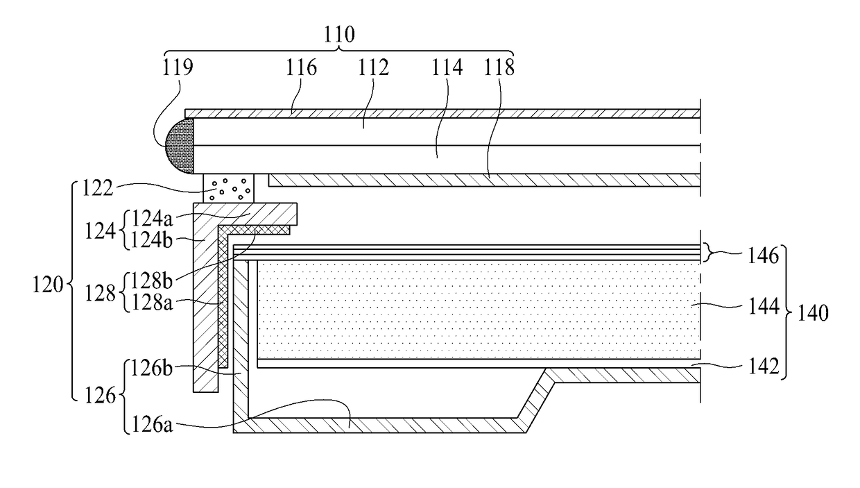
[0054]FIG. 4 is a cross sectional view along A-A line of FIG. 3, which is a cross sectional view showing one side where a sheet supporting groove is not prepared in the display device according to the present invention.

[0055]Referring to FIG. 4, the display device according to the first embodiment of the present invention may include a display panel 110, a panel supporter 120, and a backlight unit 140.

[0056]The display panel 110 displays a predetermined image by the use of light emitted from the backlight unit 140. The display panel 110 may include confronting upper and lower substrates 112 and 114 bonded to each other with a liquid crystal layer interposed in-between, an upper polarizing member 116 attached to the upper substrate 112, a lower polarizing member 118 attached to the lower substrate 114, and a side sealing member 119 attached to a lateral surface of the upper substrate 112.

[0057]The upper substrate 112 is a color filter array substrate, wherein an area of the upper sub...

second embodiment

[0084]FIG. 6 is a cross sectional view along B-B line of FIG. 3, which is a cross sectional view showing the other side where a sheet supporting groove is prepared in the display device according to the present invention. Except for an optical control member, it is the same as that of FIG. 5 (or some variations may apply). Hereinafter, only the optical control member will be described, and a detailed description for the same parts will be omitted or may be brief.

[0085]The optical control member 128 may include a first optical control member 128a and a second optical control member 128b.

[0086]The first optical control member 128a confronts an outer surface of an optical sheet part 146 provided with a sheet fixing portion 146a. In more detail, the first optical control member 128a is prepared in an inner surface of a guide sidewall 124b confronting the outer surface of the sheet fixing portion 146a. The first optical control member 128a includes a light-reflecting material, and a siz...

third embodiment

[0089]FIG. 7 is a cross sectional view along B-B line of FIG. 3, which is a cross sectional view showing the other side where a sheet supporting groove is prepared in the display device according to the present invention. Except for an optical sheet part, it is the same as that of FIG. 5 (or some variations may apply). Hereinafter, only the optical sheet part will be described, and a detailed description for the same parts will be omitted or may be brief.

[0090]The optical sheet part 146 is provided on a light guiding plate 144. The optical sheet part 146 improves the luminance properties of light advancing from the light guiding plate 144 toward a display panel 110. The optical sheet part 146 may include at least one diffusion sheet and at least one prism sheet among a lower diffusion sheet, a lower prism sheet, an upper prism sheet, and an upper diffusion sheet. The optical sheet part 146 may include a sheet fixing portion 146a and a light absorbing layer 147.

[0091]The sheet fixing...


PUM


Abstract

Discussed is a display device that may include a receiving case having a bottom surface, a case sidewall, and a sheet supporting groove prepared in the case sidewall; a backlight unit including an optical sheet part with a sheet fixing portion received in the receiving case and disposed in the sheet supporting groove; a display panel disposed on the backlight unit; a guide frame for supporting rear edges of the display panel and surrounding the case sidewall; and an optical control member confronting an outer surface of the optical sheet part with the sheet fixing portion.

Description

CROSS REFERENCE TO RELATED APPLICATIONS[0001]This application claims the priority benefit of the Korean Patent Application No. 10-2015-0152353 filed on Oct. 30, 2015, which is hereby incorporated by reference as if fully set forth herein.BACKGROUND[0002]Field of the Disclosure[0003]Embodiments of the present invention relate to a display device, and more particularly, to a display device capable of improving a picture quality.[0004]Discussion of the Related Art[0005]Generally, a display device displays an image by the use of thin film transistor functioning as a switching element. The display device is widely used as display devices of notebook computer, tablet computer, smart phone, portable display device, and portable information device as well as display devices of television or monitor. The display device may not be a self light emitting display device, and in such cases, may include a backlight unit for emitting light, which is disposed under a display panel. That is, the disp...

Claims


Application Information

Patent Timeline
Patent Type & Authority Applications(United States)
IPC IPC(8): F21V8/00
CPCG02B6/0088G02B6/0051G02B6/0055G02F1/133308G02F1/133512G02F1/133553G02F1/133606G02F1/133317G02F1/133609G02B6/0086G02B6/005G02B6/0001G02B6/0053G02B6/0081G02B6/0093G02F1/133611G02F1/133608
Inventor JEON, HYEONKUSHIN, JUNGCHUL
Owner LG DISPLAY CO LTD
Why Eureka
Try Eureka