Light emitting display apparatus
a technology of light-emitting display and display screen, which is applied in the direction of electrical equipment, basic electric elements, and semiconductor devices, etc., can solve the problems of color realization ratio and picture quality, color realization ratio may be deteriorated, and color mixture may occur, so as to prevent color mixture, improve the aperture ratio of the pixel, and prevent leakage current
- Summary
- Abstract
- Description
- Claims
- Application Information
AI Technical Summary
Benefits of technology
Problems solved by technology
Method used
Image
Examples
first embodiment
[0140]The wavelength conversion layer 150 according to the present disclosure includes a color filter which transmits only the wavelength having a color preset in the pixel from the light emitted from the self-light emitting portion EP toward the substrate 100. For example, the wavelength conversion layer 150 may transmit only the red wavelength, green wavelength, or blue wavelength. As an embodiment, in the light emitting display apparatus according to the present disclosure, when the one unit pixel comprises the adjacent first to third pixels, the wavelength conversion layer prepared in the first pixel may include a red color filter, the wavelength conversion layer prepared in the second pixel may include a green color filter, and the wavelength conversion layer prepared in the third pixel may include a blue color filter. Additionally, in the light emitting display apparatus according to the present disclosure, the one unit pixel may further include a white pixel without the wavel...
second embodiment
[0141]The wavelength conversion layer 150 according to the present disclosure may include a quantum dot having a size capable of re-emitting light according to light emitted from the light emitting element ED to the substrate 100 and discharging light of a color which is set for the pixel. For example, the quantum dot may be selected from CdS, CdSe, CdTe, CdZnSeS, ZnS, ZnSe, GaAs, GaP, GaAs—P, Ga—Sb, InAs, InP, InSb, AlAs, AlP, or AlSb. For example, the wavelength conversion layer of the first pixel may include a quantum dot of CdSe or InP, the wavelength conversion layer of the second pixel may include a quantum dot of CdZnSeS, and the wavelength conversion layer of the third pixel may include a quantum dot of ZnSe. Thus, the light emitting display apparatus in which the wavelength conversion layer 150 includes quantum dots may realize high color realization ratio (or the color gamut).
third embodiment
[0142]The wavelength conversion layer 150 according to the present disclosure may include a color filter having a quantum dot.
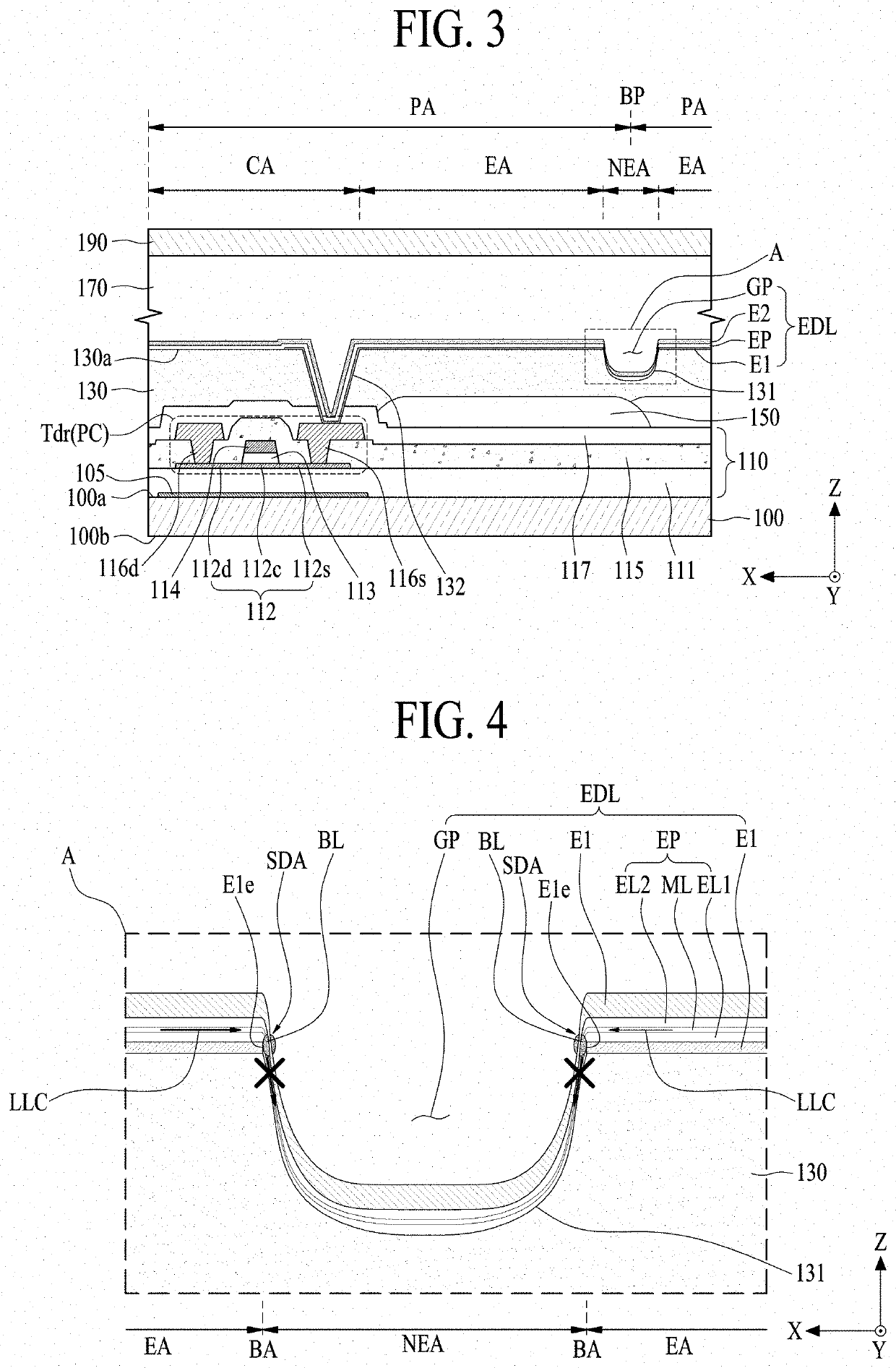
[0143]The wavelength conversion layer 150 according to an embodiment of the present disclosure may be overlapped with the area between the adjacent pixel areas PA. For example, the wavelength conversion layer 150 disposed in each pixel area PA may be overlapped with another wavelength conversion layer 150 disposed in another pixel area PA in the non-emission area NEA of the adjacent pixel area PA. For example, the wavelength conversion layer 150 disposed in each pixel area PA and another wavelength conversion layer 150 disposed in another adjacent pixel area PA may be overlapped with each other under (or below) the groove 131 of the planarization layer 130. The overlap area between the wavelength conversion layers 150 disposed in the adjacent pixel areas PA may function as a color mixture prevention area between the adjacent pixels. For example, the overlap a...
PUM
| Property | Measurement | Unit |
|---|---|---|
| distance | aaaaa | aaaaa |
| depth | aaaaa | aaaaa |
| thickness | aaaaa | aaaaa |
Abstract
Description
Claims
Application Information
 - R&D
- Intellectual Property
- Life Sciences
- Materials
- Tech Scout
- Unparalleled Data Quality
- Higher Quality Content
- 60% Fewer Hallucinations
Browse by: Latest US Patents, China's latest patents, Technical Efficacy Thesaurus, Application Domain, Technology Topic, Popular Technical Reports.
© 2025 PatSnap. All rights reserved.Legal|Privacy policy|Modern Slavery Act Transparency Statement|Sitemap|About US| Contact US: help@patsnap.com


