Light-emitting element and display device using same
a technology of light-emitting elements and display devices, which is applied in the direction of discharge tubes/lamp details, organic semiconductor devices, discharge tubes/lamp details, etc., can solve the problems of large amount of light generated at the light-emitting layers, loss of display systems, and ineffective use of display lights, etc., to achieve good efficiency, improve light extraction ratio, and high picture quality
- Summary
- Abstract
- Description
- Claims
- Application Information
AI Technical Summary
Benefits of technology
Problems solved by technology
Method used
Image
Examples
first embodiment
The First Embodiment
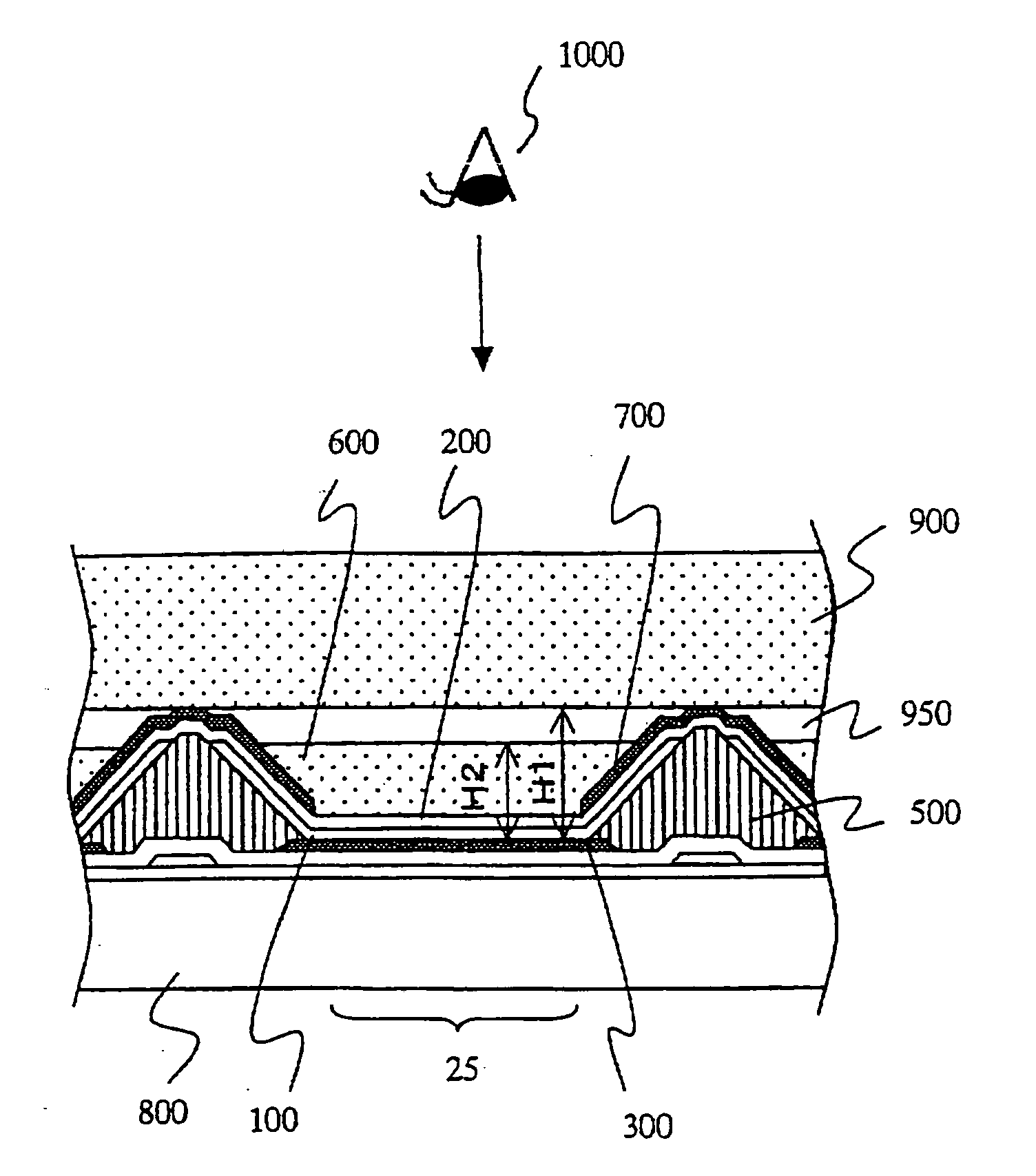
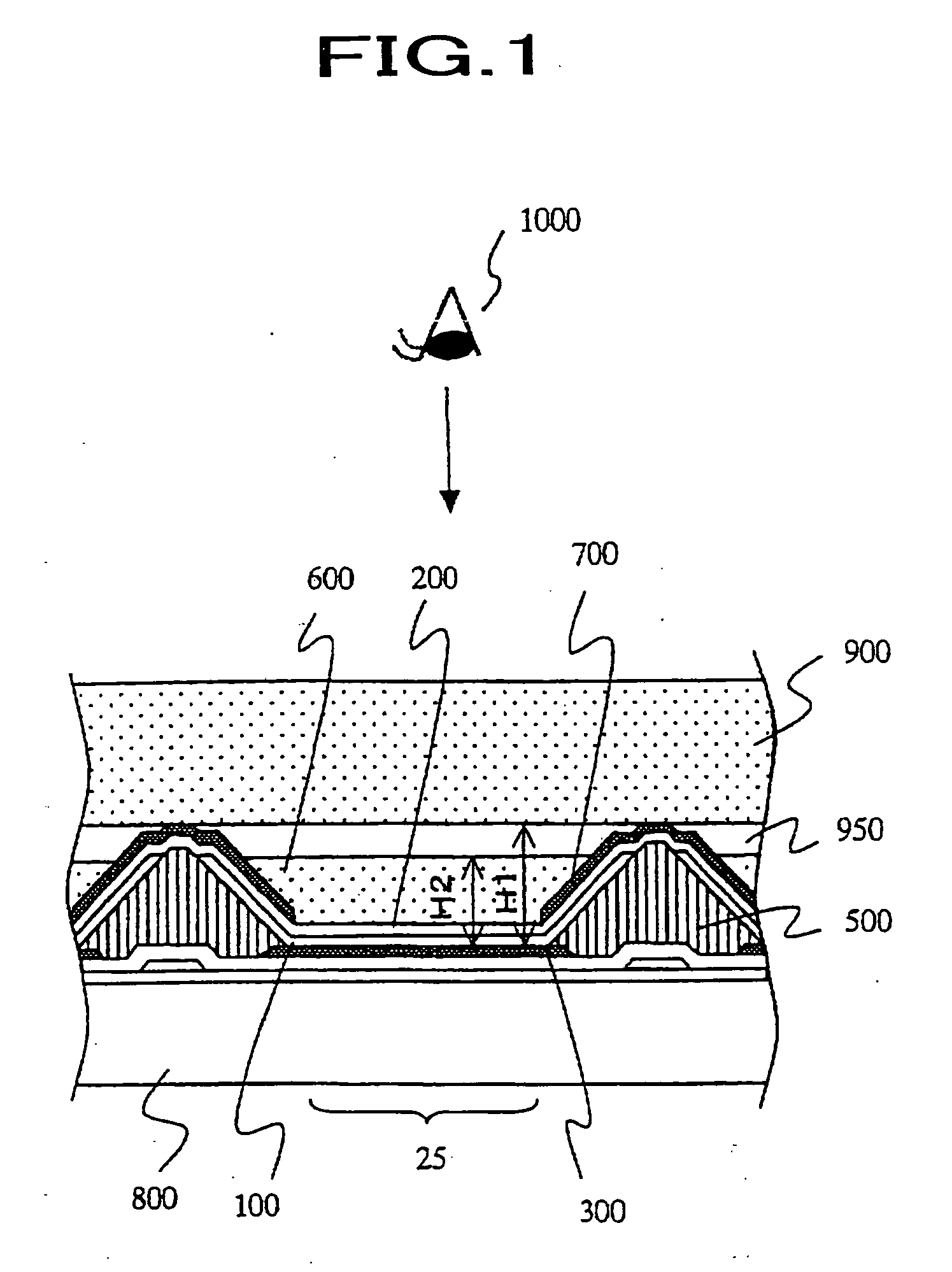
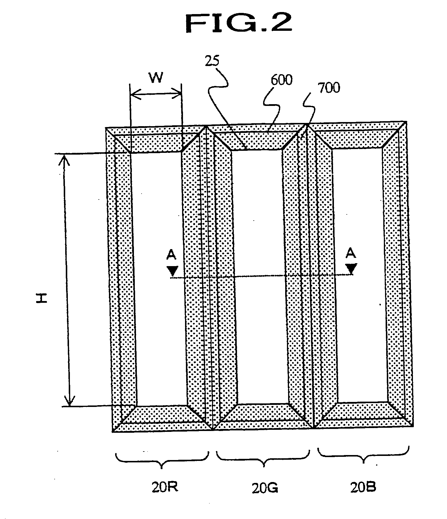
[0047]FIG. 1 shows the cross sectional view of one picture element explaining the first embodiment of this invention. FIG. 2 shows another drawing explaining the first embodiment. FIG. 1 corresponds to the cutaway view along the line of A-A in FIG. 2. One color picture element consists of three picture elements of red-light-emitting picture element 20R, green-light-emitting picture element 20G and blue-light-emitting picture element 20B which are arranged in side-by-side as shown in FIG. 2 and the predetermined color is presented by additive color mixing of the lights emitted from these three picture elements. In addition, these picture elements 20R, 20G and 20B are called as unit picture elements or sub-pixels and a unit picture element corresponds to a mono-chromatic picture element for the case of mono-chromatic display device.
[0048] For the display device according to the present invention, wires, switching elements, storage capacitors and insulating layers ...
second embodiment
The Second Embodiment
[0101] Next, we will explain another embodiment of the display device regarding to this invention. FIG. 17 shows a cross sectional view of another embodiment of the display device. In this display device, the height H3 of the optical waveguide layer locating at the central area of the basin area surrounded by the bank 500 is continuously larger as being closer to the bank 500. Besides the height H4 of the optical waveguide layer 600 on the tilted reflective surface 700 is larger than H3, we will use the same signs and notations for the same portions and omit the detailed explanation.
[0102] For the optical waveguide layer 600 which satisfies the relation of these heights, we can form it by controlling the dry out speed of the coated optical waveguide layer compound material when we coat the optical waveguide layer compound consisting of binder resin and solvent with taking the boiling point and the vapor pressure of the solvent in the room temperature into accou...
third embodiment
The Third Embodiment
[0105] Next, we will further explain another embodiment of the display device regarding to this invention. FIG. 20 shows a cross sectional view of a picture element in this another embodiment. For this embodiment of the display device, the thickness of the optical waveguide layer has the maximum at the center of the area surrounded by the bank 500 and is continuously less as being closer to the bank. Since the fundamental construction is same as the embodiment described above besides the shape of the optical waveguide layer is convex, we mark with the same signs and notations to the same portions and avoid the explanation. This shape of the optical waveguide layer is made by making the tilted reflective surface 700 liquid-repellent and the transparent electrode 200 exposing to the optical waveguide layer liquid-wettable before coating the optical waveguide layer compound material consisting of binder resin and solvent. As a concrete process, the substrate is expo...
PUM
 Abstract
Description
Claims
Application Information
 - R&D
- Intellectual Property
- Life Sciences
- Materials
- Tech Scout
- Unparalleled Data Quality
- Higher Quality Content
- 60% Fewer Hallucinations
Browse by: Latest US Patents, China's latest patents, Technical Efficacy Thesaurus, Application Domain, Technology Topic, Popular Technical Reports.
© 2025 PatSnap. All rights reserved.Legal|Privacy policy|Modern Slavery Act Transparency Statement|Sitemap|About US| Contact US: help@patsnap.com


