System and method for providing aqueous stream purification services

a technology of aqueous stream and purification service, which is applied in the direction of dispersed particle filtration, combination devices, feed/discharge of settling tanks, etc., can solve the problems of contaminated water sources that cannot be simply dumped on the ground or pumped back into wells, contaminated water sources that present additional operation and expense for oil and gas well owners and operators, and achieve energy-intensive distillation process , the effect of efficient way of processing waste water

Active Publication Date: 2009-03-26
H2OIL
View PDF23 Cites 22 Cited by
  • Summary
  • Abstract
  • Description
  • Claims
  • Application Information

AI Technical Summary

Benefits of technology

[0007]From the foregoing discussion, it should be apparent that a need exists for a system and method that provides aqueous stream purification services. Beneficially, such a system and method would provide oil and gas producers a more efficient way to process waste water. Such a system and method would provide a source of clean water for use in further well operations, for human and agricultural needs, or for reinjection into the ground. Further, such a system and method could be used to process waste water in settings other than the petroleum industry. The system and method could be used when circumstances call for a self-contained purification system.

Problems solved by technology

Due to environmental concerns, contaminated water cannot simply dumped on the ground or pumped back into wells.
The requirement to treat contaminated water sources presents an additional operation and expense for oil and gas well owners and operators.
Distillation is an energy-intensive process that frequently requires large distillation columns.
All of these constraints cost money and increase the cost of oil and gas production.

Method used


Image

  • System and method for providing aqueous stream purification services
  • System and method for providing aqueous stream purification services
  • System and method for providing aqueous stream purification services

Examples


Embodiment Construction

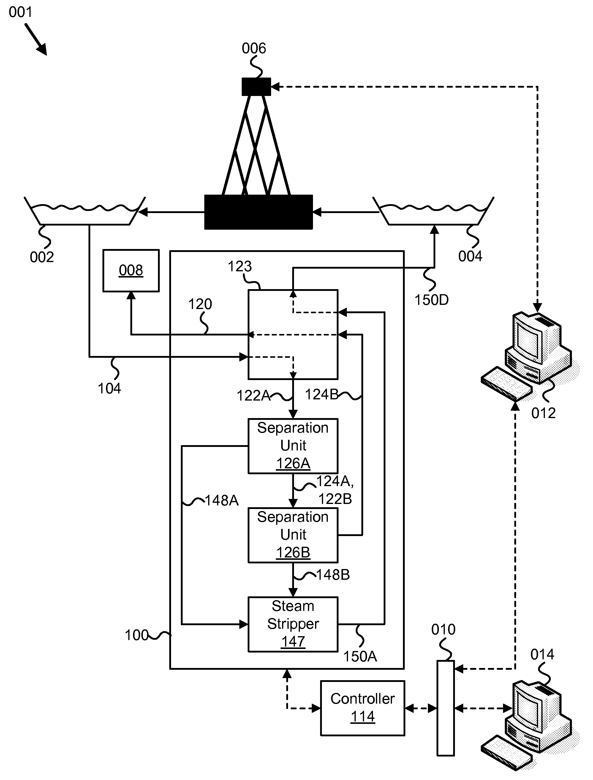
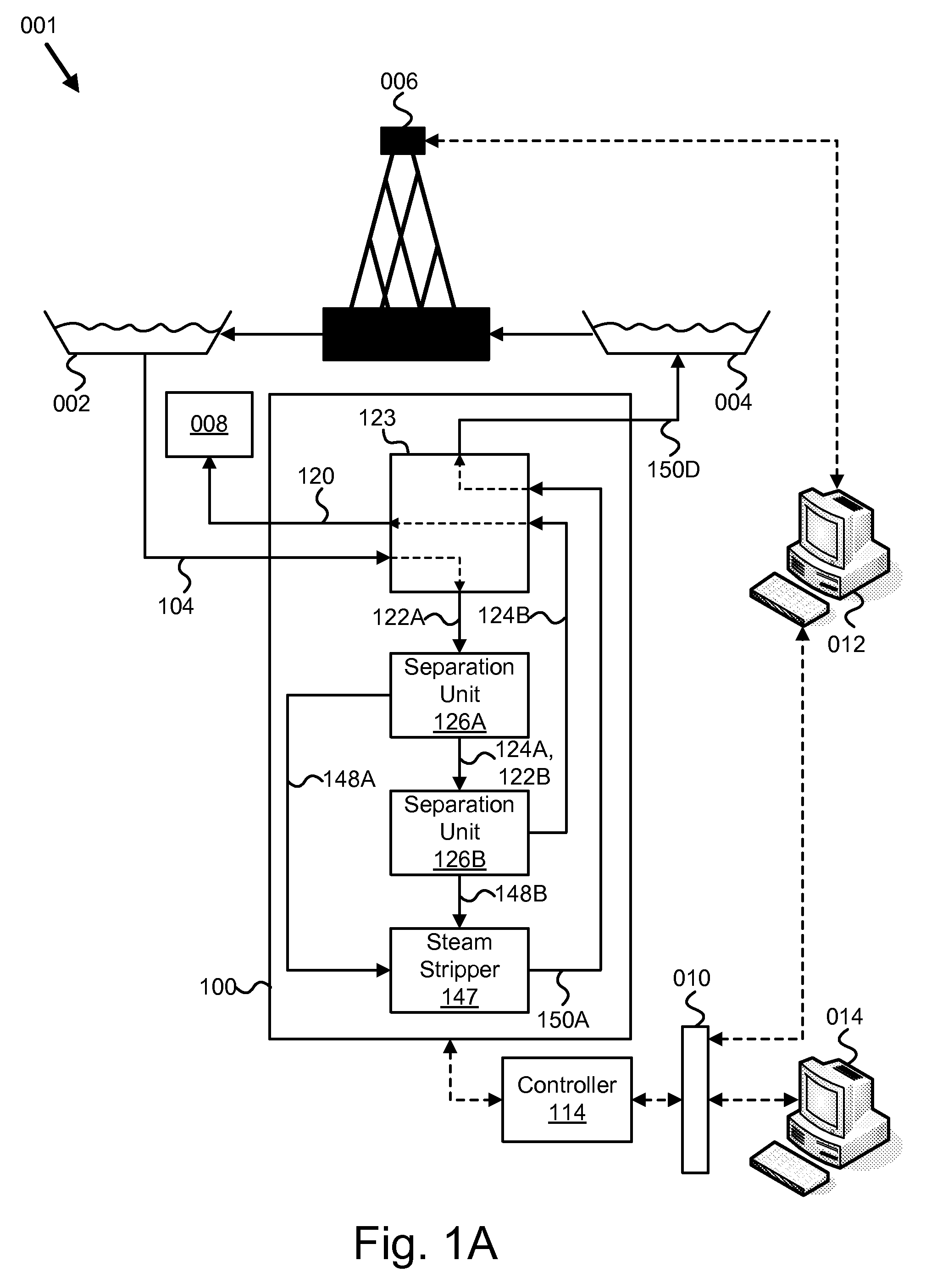
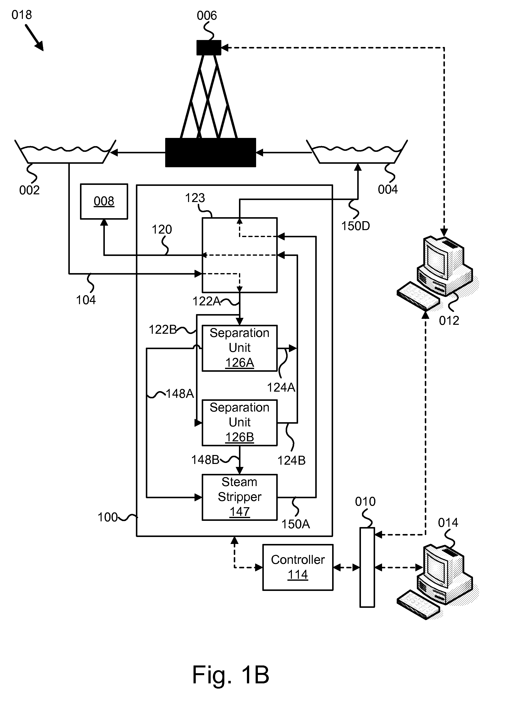
[0034]It will be readily understood that the components of the present invention, as generally described and illustrated in the figures herein, may be arranged and designed in a wide variety of different configurations. Thus, the following more detailed description of the embodiments of the apparatus, system, and method of the present invention, as presented in FIGS. 1 through 6B, is not intended to limit the scope of the invention, as claimed, but is merely representative of selected embodiments of the invention.

[0035]Reference throughout this specification to “one embodiment” or “an embodiment” means that a particular feature, structure, or characteristic described in connection with the embodiment is included in at least one embodiment of the present invention. Thus, appearances of the phrases “in one embodiment” or “in an embodiment” in various places throughout this specification are not necessarily all referring to the same embodiment.

[0036]Furthermore, the described features,...


PUM

PropertyMeasurementUnit
mass flow rateaaaaaaaaaa
temperatureaaaaaaaaaa

Abstract

A system and method are disclosed for providing aqueous stream purification services. The system includes at least one separation unit. Each separation unit may include a mechanical vapor recompression separator, a steam stripper, and a secondary recovery heat exchanger. The system for wastewater purification may receive water from a waste water storage, purify the water, and return the purified water to a purified water storage. The system may include a controller. The controller may include an operating conditions module configured to interpret at least one operating condition. Operating conditions may be waste fluid stream impurity concentrations, waste fluid stream flow rates, steam inlet temperatures, recirculation stream flow rates corresponding to the at least one separation unit, recirculation stream temperatures corresponding to the at least one separation unit, purified product stream flow rates, purified product stream impurity concentrations, and/or purge stream concentrations corresponding to the at least one separation unit.

Description

CROSS-REFERENCES TO RELATED APPLICATIONS[0001]This application claims the benefit of U.S. Provisional Patent Application No. 60 / 968,285 entitled “APPARATUS, SYSTEM, AND METHOD FOR PROVIDING AQUEOUS STREAM PURIFICATION SERVICES” and filed on Aug. 27, 2007, for Larry D. Sanderson, et. al which is incorporated herein by reference. The application incorporates by reference U.S. Provisional Application Ser. No. 60 / 968,284 filed Aug. 27, 2007.BACKGROUND OF THE INVENTION[0002]1. Field of the Invention[0003]This invention relates to waste stream purification, and more particularly relates to purification of waste streams containing contaminants typically found in oilfield applications.[0004]2. Description of the Related Art[0005]Water is often used for various tasks in the oil and gas industry. For example, water may be injected into a well to repressurize a reservoir, and water may be pumped from a well in the process of extracting oil or gas. As another example, water may used to deliver ...

Claims


Application Information

Patent Timeline
Patent Type & Authority Applications(United States)
IPC IPC(8): G05B23/00
CPCB01D1/16B01D19/0005C02F1/048C02F2209/42C02F2209/02C02F2209/03C02F2209/40C02F2103/365Y02P70/10
Inventor SANDERSON, LARRY D.SCHLEIFFARTH, JAMES W.MERRILL, LESLIE D.ROHWER, BRADFORD M.
Owner H2OIL
Why Eureka
Try Eureka