Surgical Implants

a technology of surgical implants and intervertebral discs, applied in the field of surgical implants, can solve the problems of reduced mobility of devices, and achieve the effect of reliable spinal disc replacement and improved partial or total spinal disc replacemen

Inactive Publication Date: 2009-04-23
NUVASIVE
View PDF99 Cites 9 Cited by
  • Summary
  • Abstract
  • Description
  • Claims
  • Application Information

AI Technical Summary

Benefits of technology

[0025]One or more materials used in one or more of the filling elements may be bio-absorbable. The bio-absorbable material may be used to decrease the amount of one or more filling elements present and / or positions at which one or more filling elements is present and / or density at which one or more filling elements is present overtime. The bio-absorbable material may restrain one or more of the filling elements, or a part thereof, in a first state, the bio-absorption of the material allowing one or more filling elements, or a part thereof, to assume a second state. The second state may provide a greater internal volume for one or more filling elements and / or greater porosity for one or more filling elements and / or reduction in mass of one or more filling elements and / or provide more space for tissue ingrowth.
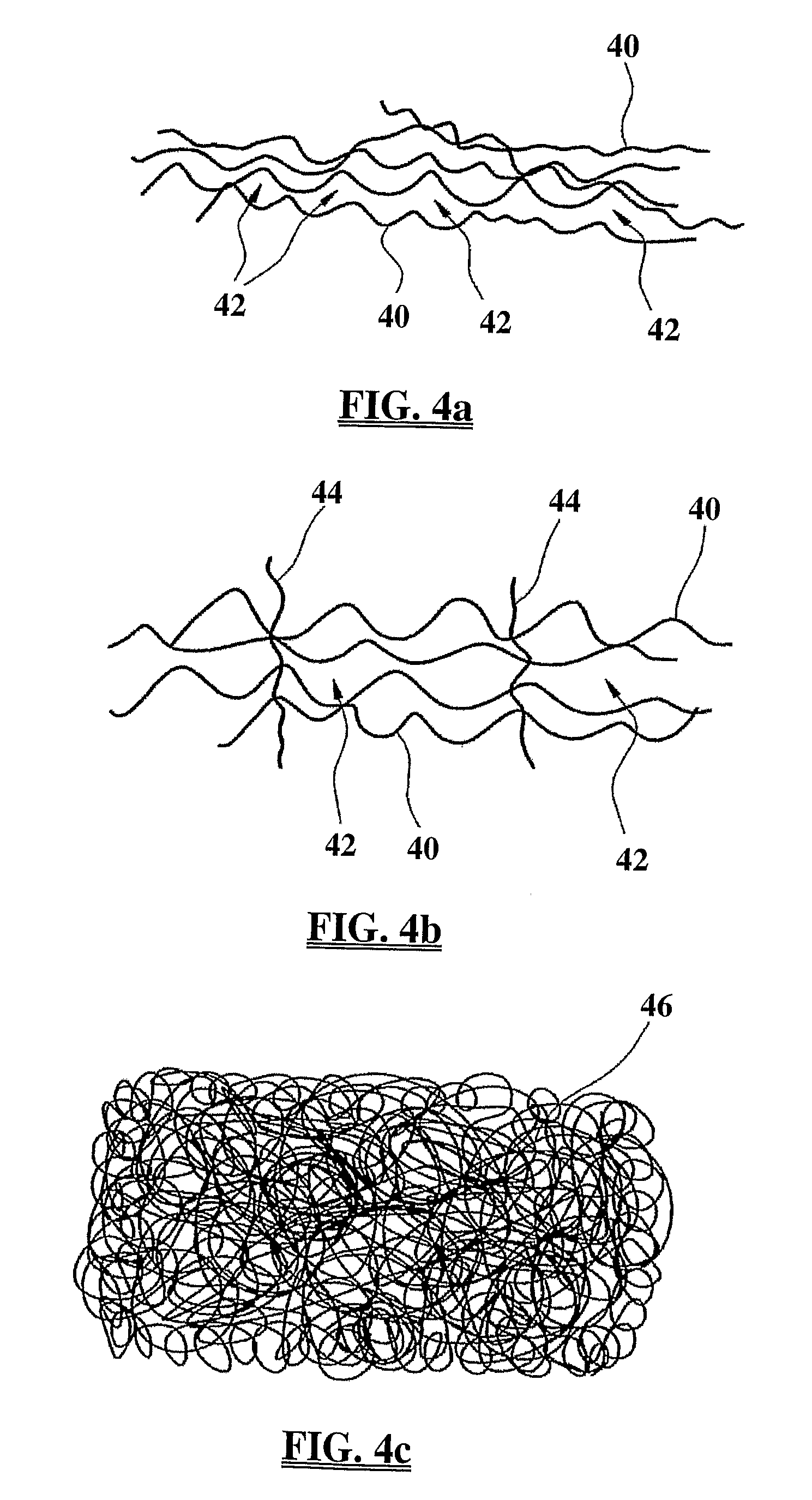
[0036]One or more materials used in the inner component may be bio-absorbable and / or soluble and / or degradable, particularly with the spine. The bio-absorbable material may be used to decrease the amount of inner component present and / or positions at which the inner component is present and / or density at which the inner component is present overtime. Areas of bio-absorbable material may be provided. Bio-absorbable fibres may be used to form the inner component. The inner component may be entirely bio-absorbable or only partially. Different materials having different rates of bio-absorption may be used. The may be mixed together in the inner component and / or may be used for particular areas thereof and / or in a particular sequence within the inner component. Slow, moderate and fast bio-absorption materials may be used. Preferably bio-absorption of the inner component is used to provide space for tissue ingrowth.
[0054]One or more materials used in the outer component may be bio-absorbable and / or soluble and / or degradable, particularly with the spine. The bio-absorbable material may be used to decrease the amount of outer component present and / or positions at which the outer component is present and / or density at which the outer component is present overtime. Areas of bio-absorbable material may be provided. Bio-absorbable fibres may be used to form the outer component. The outer component may be entirely bio-absorbable or only partially. Different materials having different rates of bio-absorption may be used. The may be mixed together in the outer component and / or may be used for particular areas thereof and / or in a particular sequence within the outer component. Slow, moderate and fast bio-absorption materials may be used. Preferably bio-absorption of the outer component is used to provide space for tissue ingrowth.
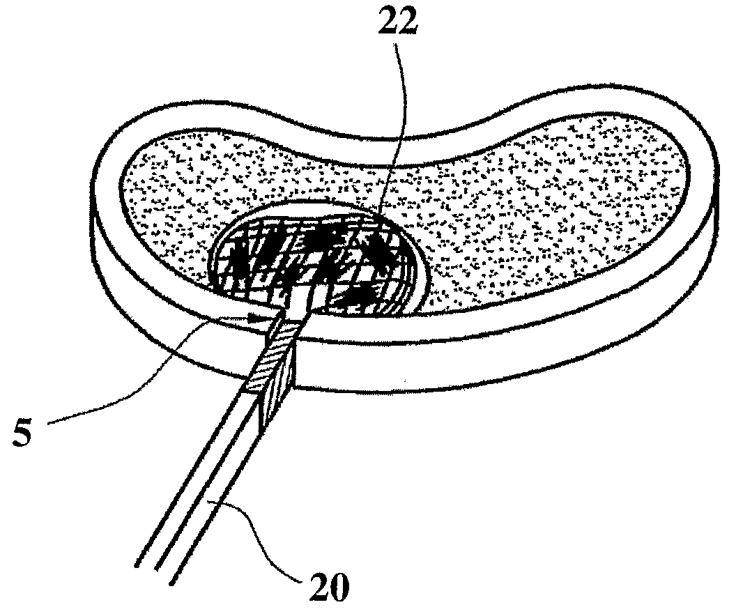
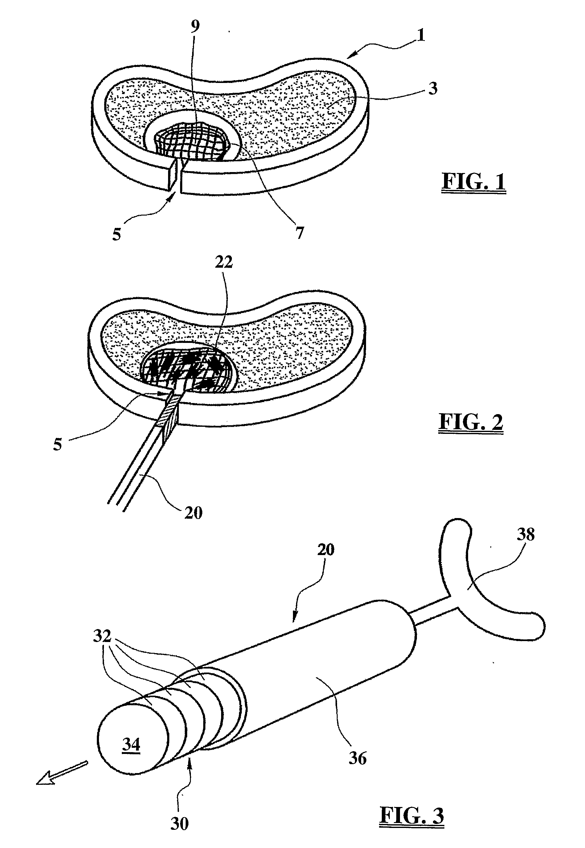
[0103]Whilst the inner and / or outer component can be entirely flexible, consistent with its fabric / textile nature, there are benefits in providing a more defined structure or profile to one or both of these components. Thus, as shown by way of example the outer component is provided of fabric, but within the bag a number of stiffening elements are provided. Thus a series of stiffening elements are provided in the form of rings which extend around the periphery of the outer component and so seek to maintain the side wall profile of the outer component. For insertion, the sides of the rings can be squeezed together and so reduce the cross-section of the outer component. Once inside the disc space, the compression can be removed and the rings will push the sides of the outer component outwards to the disc like profile. This assists in ensuring the shape of the implant is correct and assists in providing the space into which the filling elements can be introduced.
[0104]The stiffening elements may also be configured to push the top and bottom rings apart in a vertical sense. Again a downward compression can be used to reduce the profile of the outer component, with the removal of that compression allowing the outer component to return to the desired form.
[0105]Such arrangements of stiffening elements can be used to close or assist in supporting the closure of the inner and / or outer component. Equally, such stiffening elements can be used to support surfaces of the inner and / or outer component against loads. For instance, the surface of the implant which faces the vertebra above the implant in a standing individual and / or the surface which faces the vertebra below may be provided with stiffening elements which extend across them to resist loads. Stiffening elements down the sides, round the edges and at other positions may also be provided to support the shape of the implant and / or contribute to its functional characteristics. Resistance to load, extension, compression, flexion or the like may be provided in this way, as might resistance to tissue ingrowth pressures.

Problems solved by technology

Generally such devices face problems in terms of the reduced mobility they provide, are reliant upon absolutely correct positioning and do not emulate fully the normal motion they aim to replace.

Method used


Image

  • Surgical Implants
  • Surgical Implants
  • Surgical Implants

Examples


Embodiment Construction

[0146]Illustrative embodiments of the invention are described below. In the interest of clarity, not all features of an actual implementation are described in this specification. It will of course be appreciated that in the development of any such actual embodiment, numerous implementation-specific decisions must be made to achieve the developers' specific goals, such as compliance with system-related and business-related constraints, which will vary from one implementation to another. Moreover, it will be appreciated that such a development effort might be complex and time-consuming, but would nevertheless be a routine undertaking for those of ordinary skill in the art having the benefit of this disclosure. The systems disclosed herein boast a variety of inventive features and components that warrant patent protection, both individually and in combination.

[0147]The prior art contains examples of elastomeric discs, with the motion of the elastomer being contained by bonding it to me...


PUM

PropertyMeasurementUnit
angleaaaaaaaaaa
angleaaaaaaaaaa
timeaaaaaaaaaa

Abstract

Disc prostheses, particularly for use in the lumbar region of the spine are provided. The disc prosthesis includes a core comprising one or more filling elements provided within an inner component of fabric. The inner component is provided within an outer component of fabric. By providing a smooth inner contact surface between the inner component and the core filling, movement between the inner and outer components is facilitated in preference to movement between the inner component and core. Core abrasion is thus avoided. The use of an inner component and an outer component also means that the characteristics of each can be optimised to meet different aims.

Description

CROSS REFERENCE TO RELATED APPLICATIONS[0001]The present invention is an International Patent Application and claims the benefit of priority from commonly owned and co-pending British Patent Application No. 0511329.5, entitled “Improvements Relating in and to Surgical Implants” and filed on Jun. 3, 2005, and commonly owned and co-pending British Patent Application No. 0514891.1, entitled “Improvements Relating in and to Implants” and filed Jul. 20, 2005, the entire contents of which are hereby expressly incorporated by reference into this disclosure as if set forth in their entirety herein.BACKGROUND OF THE INVENTION[0002]I. Field of the Invention[0003]This invention concerns improvements in and relating to surgical implants, particularly, but not exclusively in relation to surgical implants for the replacement of intervertebral discs, particularly, but not exclusively in the lumbar region of the spine.[0004]II. Discussion of the Prior Art[0005]Increasingly there is a desire to addr...

Claims


Application Information

Patent Timeline
Patent Type & Authority Applications(United States)
IPC IPC(8): A61F2/44A61B17/04A61B19/00
CPCA61F2/30724A61F2310/00329A61F2/30965A61F2/441A61F2/442A61F2/4611A61F2002/30008A61F2002/30009A61F2002/30062A61F2002/30069A61F2002/3008A61F2002/30092A61F2002/30146A61F2002/30225A61F2002/30242A61F2002/30291A61F2002/30298A61F2002/30461A61F2002/30462A61F2002/30565A61F2002/30578A61F2002/30583A61F2002/30588A61F2002/30601A61F2002/30602A61F2002/30616A61F2002/30841A61F2002/444A61F2002/4495A61F2210/0004A61F2210/0014A61F2210/0085A61F2220/0075A61F2230/0017A61F2230/0069A61F2230/0071A61F2230/0091A61F2250/0017A61F2250/0028A61F2250/0098A61F2310/00011A61F2/30767A61F2002/30006
Inventor MCLEOD, ALANREAH, CHRISTOPHER
Owner NUVASIVE
Why Eureka
Try Eureka