Golf club shaft having multiple metal fiber layers

a golf club shaft and metal fiber technology, applied in the field of composite resin/fiber golf club shafts, can solve the problems of difficult to overcome the design problems of conventional fiber reinforced resin technology, difficult to achieve conventional technology, and high cost of methods, so as to achieve high modulus of elasticity, increase kick, and increase mass

Inactive Publication Date: 2005-09-08
CHENG MICHAEL H L
View PDF3 Cites 5 Cited by
  • Summary
  • Abstract
  • Description
  • Claims
  • Application Information

AI Technical Summary

Benefits of technology

[0006] The general object of the present invention is to provide a golf club shaft that eliminates, for practical purposes, the aforementioned problems. In particular, one object of the present invention is to provide a golf club shaft with more mass in and around the tip section than conventional shafts. Another object of the present invention is to provide a golf club shaft with increased kick that does not require a large number of carbon fibers with a high modulus of elasticity. Still another object of the present invention is to provide a golf club shaft which facilitates precise location of the flex point.
[0007] In order to accomplish these and other objectives, a golf club shaft in accordance with the present invention includes a plurality of fiber reinforced resin layers and respective pluralities of at least first and second metal fibers that are different from one another in at least one way. Use of the metal fibers allows golf club shafts to manufactured with certain properties that correspond to the fibers themselves. Use of the metal fibers also allows these properties to be achieved in a manner that is easier, more accurate, and more cost effective than can be achieved with conventional fiber reinforced resin manufacturing techniques.
[0008] For example, one embodiment of the present invention includes three different groups of metal fibers, i.e. a plurality of relatively heavy metal fibers, a plurality of relatively stiff metal fibers and a plurality of relatively resilient metal fibers. The ends of the metal fibers are aligned with the tip. The relatively heavy metal fibers preferably extend about 5 inches to about 8 inches from the tip and are primarily used to increase the mass of the shaft in and around the tip section. The relatively stiff metal fibers, which are primarily used to define the flex point of the shaft, preferably extend about 10 inches to about 16 inches from the tip. The relatively resilient metal fibers extend at least about 20 inches from the tip and are primarily used to increase the kick of the shaft.

Problems solved by technology

Nevertheless, manufactures are faced with a variety of design issues that have proven difficult to overcome using conventional fiber reinforced resin technologies.
This can be difficult to accomplish with conventional technologies because composite materials are generally light.
This method is, however, very expensive.
Another design issue is the location of the shaft flex point and, more specifically, the inability of shaft designers to precisely predict the location of the flex point when designing a shaft without using excessive amounts of composite material, which can lead to weight and thickness issues.

Method used


Image

  • Golf club shaft having multiple metal fiber layers
  • Golf club shaft having multiple metal fiber layers
  • Golf club shaft having multiple metal fiber layers

Examples


Embodiment Construction

[0021] The following is a detailed description of the best presently known modes of carrying out the invention. This description is not to be taken in a limiting sense, but is made merely for the purpose of illustrating the general principles of the invention. The scope of the invention is defined by the appended claims.

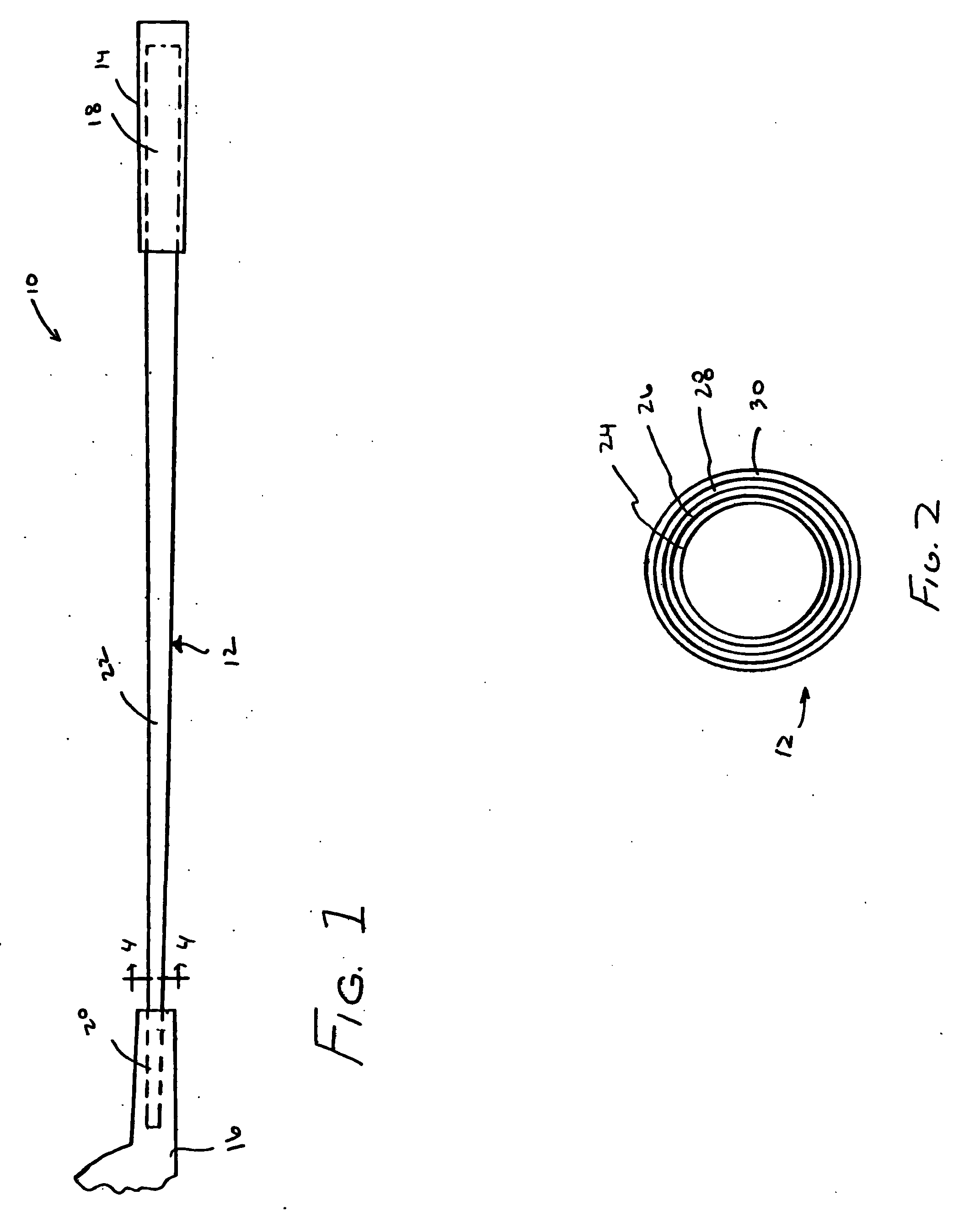
[0022] As illustrated for example in FIG. 1, a golf club shaft 10 in accordance with a preferred embodiment of the present invention includes a hollow shaft 12, a grip 14, and a club head 16. The exemplary shaft 12 is divided into three sections—the grip section 18 which is covered by the grip 14, the tip section 20 which supports the club head 16, and the main body section 22 which extends from the distal end of the grip section to the proximal end of the tip section. In the illustrated embodiment, the grip section 18 is substantially cylindrical, the tip section 20 is substantially cylindrical, and the main body section 22 has a substantially constant taper. The p...


PUM


Abstract

A golf club shaft including a fiber reinforced resin layers and a variety of metal fibers.

Description

BACKGROUND OF THE INVENTION [0001] 1. Field of Invention [0002] The present invention relates generally to golf clubs and, more particularly, to composite resin / fiber golf club shafts. [0003] 2. Description of the Related Art [0004] Many substitutes have been introduced for the hard wood shafts originally used in golf club drivers and irons. Early substitute materials included stainless steel and aluminum. More recently, carbon fiber reinforced resin shafts have become popular. Such shafts are typically hollow and consist of a shaft wall formed around a tapered mandrel. The use of fiber reinforced resin has allowed golf club manufacturers to produce shafts having varying degrees of strength, flexibility and torsional stiffness. As such, manufacturers are able to produce shafts which suit the needs of a wide variety of golfers. [0005] Nevertheless, manufactures are faced with a variety of design issues that have proven difficult to overcome using conventional fiber reinforced resin t...

Claims


Application Information

Patent Timeline
Patent Type & Authority Applications(United States)
IPC IPC(8): A63B53/00A63B53/10A63B53/12A63B59/06
CPCA63B53/10A63B59/0014A63B2209/023A63B2059/0081A63B2209/02A63B59/06A63B59/50A63B60/06A63B60/08A63B60/10A63B2102/18A63B60/0081
Inventor CHENG, MICHAEL H. L.
Owner CHENG MICHAEL H L
Why Eureka
Try Eureka