Method for producing a rotor vane for a turbomachine

a technology of a turbine engine and a rotor blade, which is applied in the direction of manufacturing tools, foundry patterns, foundry moulding apparatus, etc., can solve the problem of relatively low machining allowance and excess mass added to the blank casting, and achieve the effect of simple, effective and economical production

Active Publication Date: 2016-01-21
SN DETUDE & DE CONSTR DE MOTEURS DAVIATION S N E C M A
View PDF0 Cites 6 Cited by
  • Summary
  • Abstract
  • Description
  • Claims
  • Application Information

AI Technical Summary

Benefits of technology

[0011]The aim of the invention is in particular to provide a simple, effective and economical solution to this problem.

Problems solved by technology

Moreover, the excess mass added to the blank casting as a result of the machining allowance is relatively low.

Method used


Image

  • Method for producing a rotor vane for a turbomachine
  • Method for producing a rotor vane for a turbomachine
  • Method for producing a rotor vane for a turbomachine

Examples


Embodiment Construction

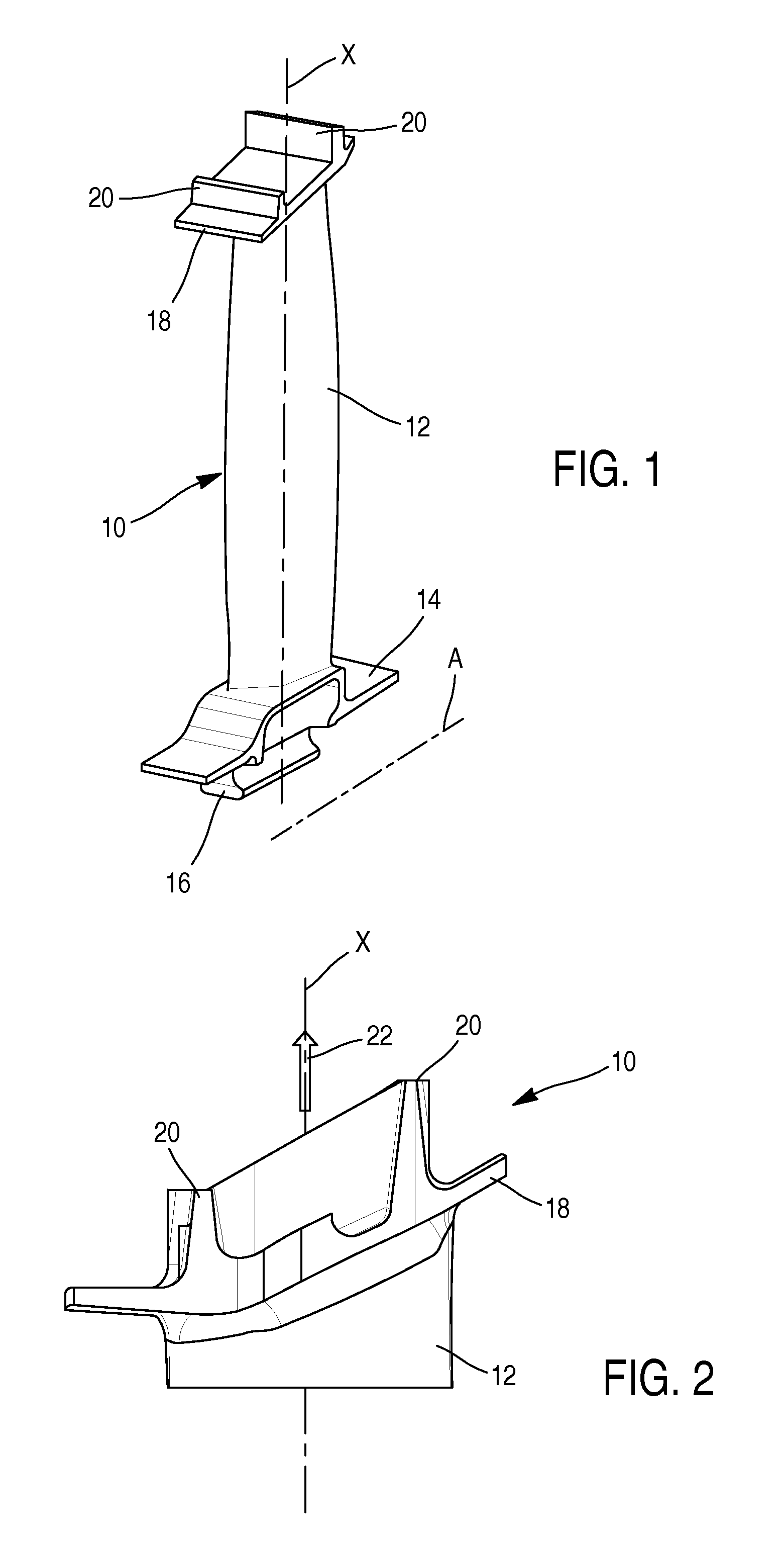
[0034]Reference is made firstly to FIG. 1 which shows a rotor blade 10 of a low-pressure turbine of a turbine engine, said blade comprising a vane 12 which is connected at one end by a platform 14 to a root 16, having a dovetail cross section in this case, and at the opposite end thereof to a heel 18 bearing knife-edge seals 20 extending radially towards the outside (relative to the longitudinal axis A of the turbine).

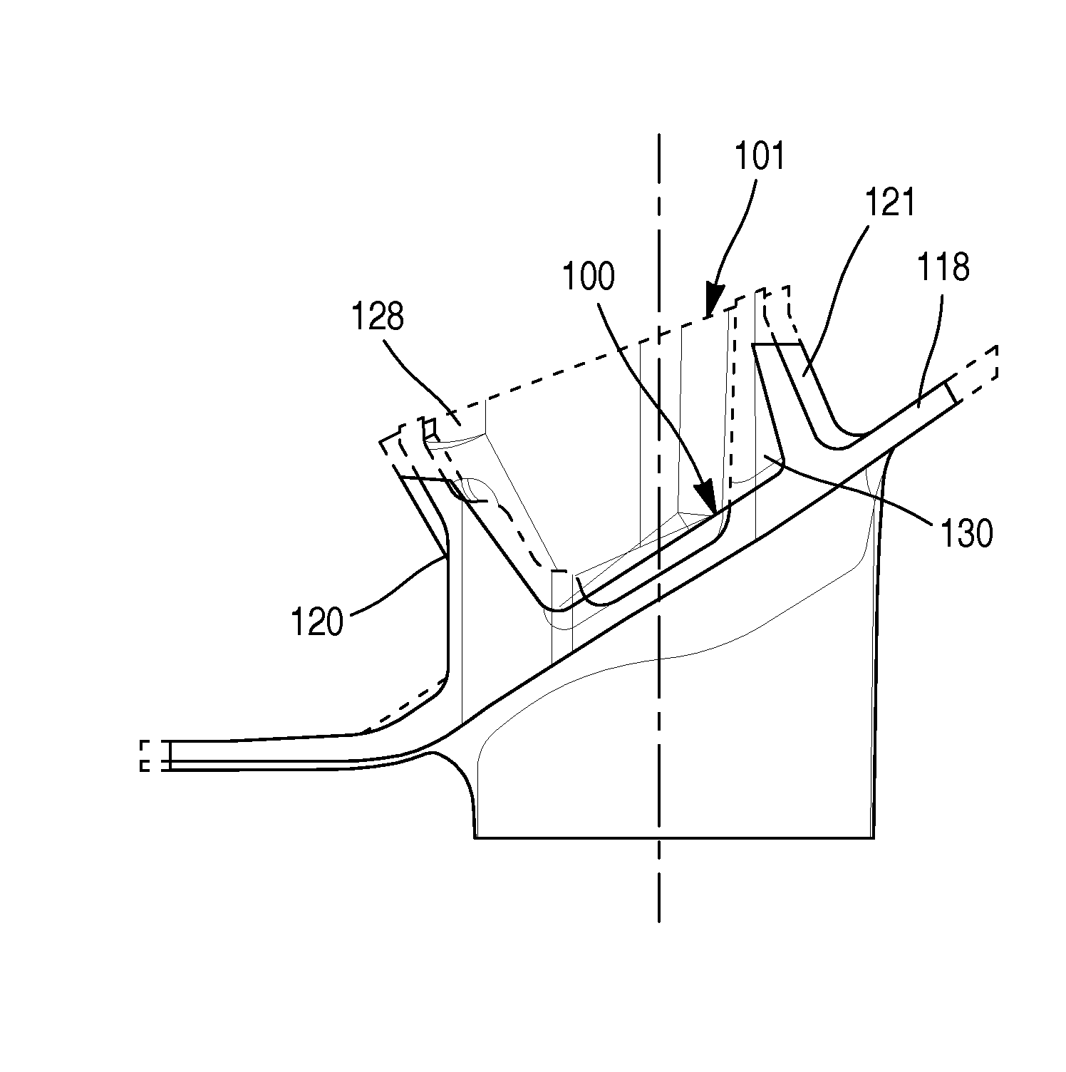
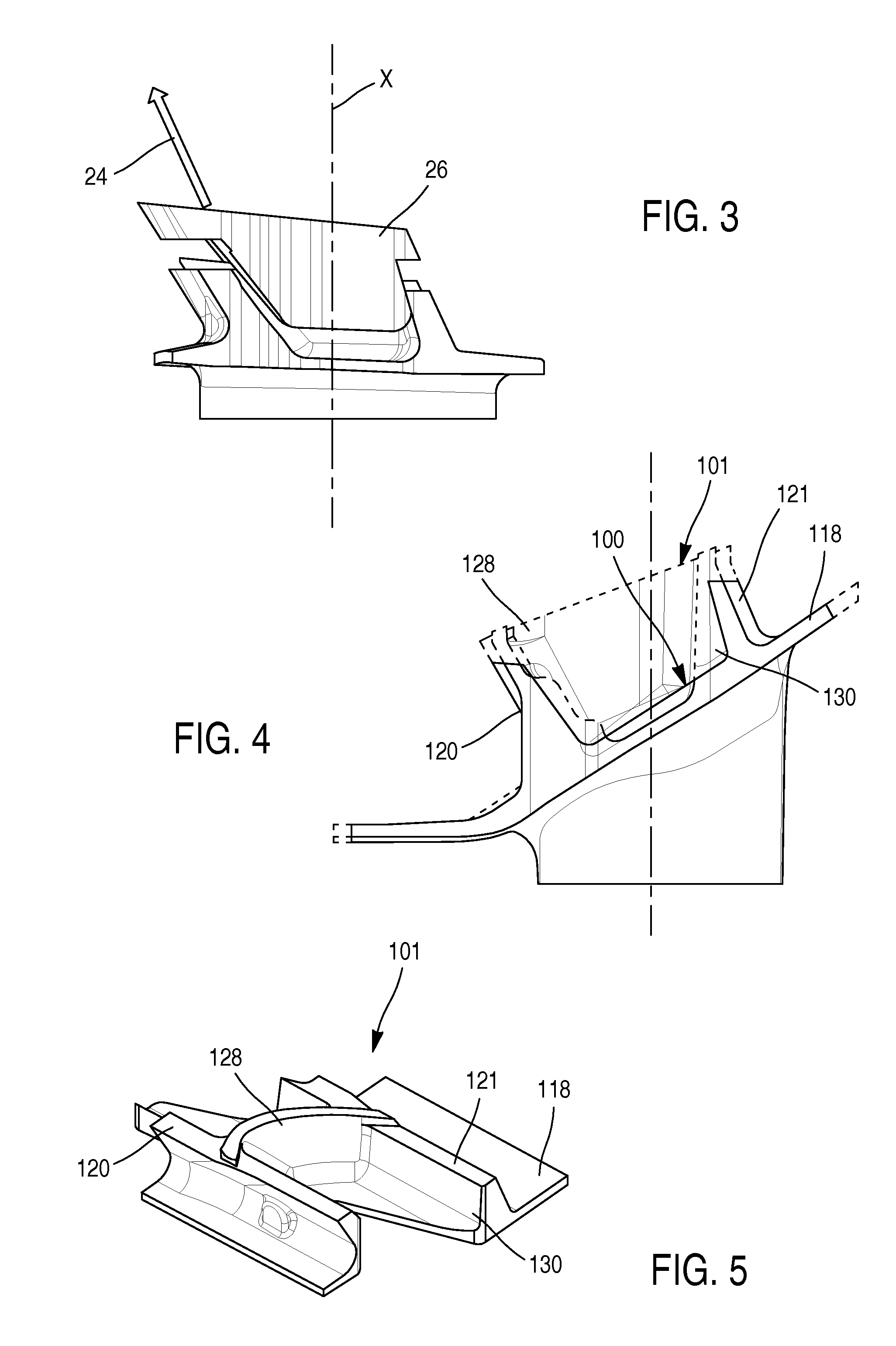
[0035]FIG. 2 shows a heel 18 of which the knife-edge seals are straight, that is to say that they extend in parallel with the longitudinal axis X of the blade, and FIG. 3 shows a heel having knife-edge seals which are inclined relative to said axis X.

[0036]The blade 10 is produced by casting, for example by a lost wax technique. The casting process makes it possible to obtain a blank casting which is to be machined for the final grading of the different portions of the blade. This process is implemented using in particular a mould comprising cavities for producing the ...


PUM

PropertyMeasurementUnit
angleaaaaaaaaaa
angleaaaaaaaaaa
thicknessaaaaaaaaaa

Abstract

The invention relates to a method for producing a rotor vane (10) for a turbomachine, comprising a step consisting in producing a rough casting, the heel of which has a downstream lip (121) with a transverse increased thickness (130) such that the lip has an upstream surface (134) substantially parallel to the above-mentioned axis, said method comprising an additional step of machining said increased thickness so that the downstream lip has an upstream surface (138) inclined in relation to the above-mentioned axis.

Description

TECHNICAL FIELD[0001]The present invention relates to a method for producing a rotor blade for a turbine engine, and in particular a rotor blade of a low-pressure turbine.PRIOR ART[0002]The prior art includes namely EP-A1-1 734 227 and FR-A1-2 977 909.[0003]A rotor blade of a low-pressure turbine comprises a vane of which one end is connected to a root by a platform and of which the opposite end is connected to a heel bearing knife-edge seals. The roots of the blades are engaged in grooves having a complementary shape, for example having a dovetail cross section, which are formed on the periphery of a disc of the turbine. The disc has an annular array of blades, the platforms of which internally delimit the stream of flow of the gases in the turbine, and the heels externally delimit said stream.[0004]The knife-edge seals of the heels extend radially outwards, relative to the longitudinal axis of the disc, and are intended to interact frictionally with a ring made of abradable materi...

Claims


Application Information

Patent Timeline
Patent Type & Authority Applications(United States)
IPC IPC(8): B22D25/02B22C9/22F01D9/02F01D11/08
CPCB22D25/02F01D9/02F05D2240/55B22C9/22F05D2240/12F01D11/08B23P15/02F01D5/225
Inventor KLEIN, GUILLAUMEBASSERY, JOSSERANDCONGRATEL, SEBASTIENDUPEYRE, RAPHAELMATHIEU, DAVIDTANG, BA-PHUC
Owner SN DETUDE & DE CONSTR DE MOTEURS DAVIATION S N E C M A
Why Eureka
Try Eureka