Sectored distributor for turbomachine

a distributor and turbomachine technology, applied in the direction of machines/engines, stators, liquid fuel engines, etc., can solve the problems of deterioration of distributor segments, difficulty in implementation, and inability to carry out certain distributors whose platforms have too complex forms, etc., to suppress the segment stelliting, simplify the replacement of members, and save resources

Active Publication Date: 2013-12-10
SN DETUDE & DE CONSTR DE MOTEURS DAVIATION S N E C M A
View PDF9 Cites 0 Cited by
  • Summary
  • Abstract
  • Description
  • Claims
  • Application Information

AI Technical Summary

Benefits of technology

[0010]This invention has in particular for purpose to provide a simple, effective and economical solution to the problems of prior art, by simplifying the replacing of the members made of abradable material of the distributor, and by suppressing the stelliting of the segments of this distributor.
[0012]In a simple manner, the annular partition of the inner platform is received in means for fastening provided on the mounting of the abradable members, which can slide on this partition. Contrary to prior art, the mounting of the abradable members is mounted in a removable manner on the partition, which facilitates the replacing of worn abradable members. It is sufficient in fact to dismount the annular mounting of the partition and to carry out the aforementioned operations of machining and brazing directly on this mounting, or simply replace this mounting carrying worn abradable members with a new mounting carrying new abradable members. The remounting of the mounting on the partition is furthermore relatively simple and rapid.
[0013]The invention further makes it possible to simplify the manufacture of each distributor segment which is obtained from foundry, as the mounting of the abradable elements is now carried out independently of these segments.
[0014]The annular mounting when it extends over several distributor segments further makes it possible to rigidify the distributor segments in such a way as to limit their vibrations and their static movements during operation, while still authorising their circumferential dilatations. It is therefore no longer required to deposit via stelliting a hard material on the means for axial bearing of the distributor segments, which makes it possible to eliminate this long and expensive operation, and to suppress the risk of deterioration of the distributor segments during this delicate operation.
[0020]Each outer wall of the mounting can be folded on the side of the annular partition in order to form an annular edge extending substantially radially towards the interior, these two annular edges being substantially parallel together and to the annular partition of the mounting. In mounting position, the partition is clamped between the outer walls or between the annular edges of the mounting, and is clamped radially between the outer walls or the annular edges of the mounting on the one hand, and the inner wall of the mounting on the other hand, which makes it possible in particular to limit the vibrations of the mounting during operation.

Problems solved by technology

With the current technique, these means for bearing comprise a very hard material called “stellite” which is deposited via a method of laser welding (“stelliting”) which is long, expensive, difficult to implement, and which risks deteriorating the distributor segments.
This technology is furthermore not able to be carried out on certain distributors of which the platforms have forms that are too complex (called 3D platforms).

Method used


Image

  • Sectored distributor for turbomachine
  • Sectored distributor for turbomachine
  • Sectored distributor for turbomachine

Examples


Embodiment Construction

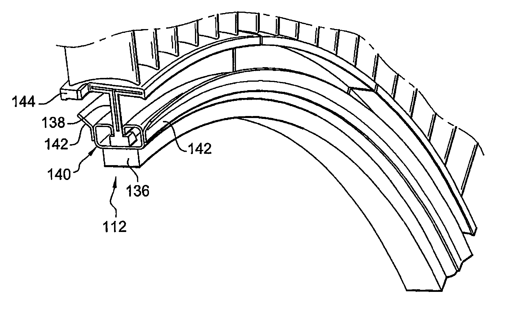
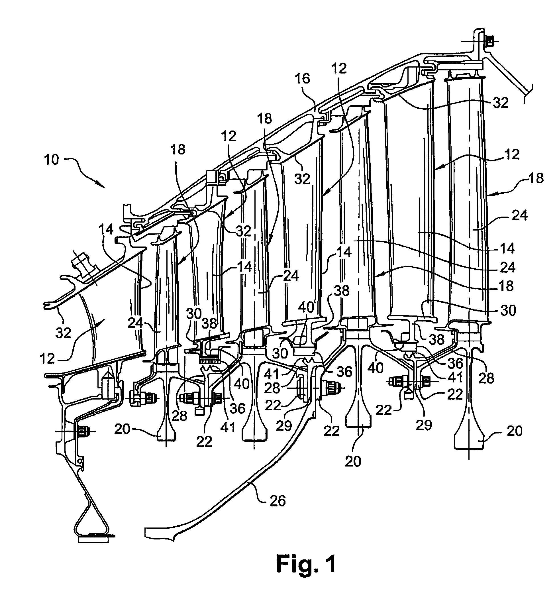
[0031]Reference is first made to FIG. 1 which shows a turbomachine low-pressure turbine 10 comprising four stages each comprising a distributor 12 carried by an outer casing 16 of the turbine and an impeller 18 located downstream of the distributor 12.

[0032]The impellers 18 include discs 20 assembled coaxially to each other by annular flanges 22 and carrying substantially radial vanes 24. These impellers 18 are connected to a turbine shaft (not shown) by the intermediary of a drive cone 26 fixed on annular flanges 22 of the discs.

[0033]Annular plates 28 for the axial retaining of the vanes 24 on the discs 20 are mounted between the discs and each include an inner radial wall 29 axially clamped between the annular flanges 22 of two adjacent discs.

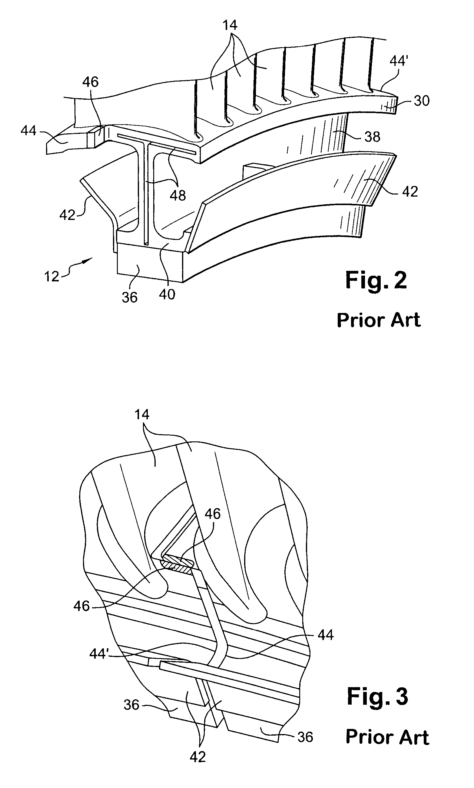
[0034]The distributors 12 each include two annular coaxial platforms 30, 32, respectively inner and outer, which delimit between them the annular stream of gas flow in the turbine and between which extend substantially radial fixed blades 14...


PUM


Abstract

The invention relates to a sectored distributor (112) for a turbomachine, including two coaxial platforms mutually connected by radial blades, the inner platform (130) being connected to an annular partition (138) for suspending an annular mounting (140) carrying elements (136) made of material subject to abrasion, this mounting sliding circumferentially on the partition and comprising a means engaging with means corresponding to the inner periphery of the partition to ensure radial restraint of the mounting on this partition.

Description

BACKGROUND OF THE INVENTION[0001]1. Field of the Invention[0002]This invention relates to a sectored distributor for a turbomachine such as a turbojet or a turboprop engine.[0003]A turbomachine comprises turbine stages each comprising a rotor impeller and a distributor, each distributor being sectored, i.e. formed of several distributor segments arranged circumferentially end-to-end.[0004]Each distributor segment comprises two coaxial annular platforms extending inside one another and connected together by substantially radial blades. The outer platform comprises means for fastening on an outer casing of the turbine. The inner platform is integral with a substantially radial annular partition which carries members made of abradable material, located radially inside the inner platform of the distributor. The members made of abradable material engage with annular lips carried by the rotor of the turbine in order to form seals of the labyrinth type.[0005]In the event of substantial wea...

Claims


Application Information

Patent Timeline
Patent Type & Authority Patents(United States)
IPC IPC(8): F01D11/02
CPCF01D9/041F01D9/042F01D11/001Y02T50/671F05D2230/60Y02T50/60
Inventor BARIAUD, CHRISTIAN BERNARDDIGARD BROU DE CUISSART, SEBASTIENHERZER, ERIC RENERICHARD, BRUNO MARIE BENJAMIN JACQUES
Owner SN DETUDE & DE CONSTR DE MOTEURS DAVIATION S N E C M A
Why Eureka
Try Eureka