
Fan for an aircraft cooling unit

a technology for cooling units and aircraft, applied in the direction of machines/engines, liquid fuel engines, couplings, etc., can solve the problems of high mass, high cost, and relatively complex shaft assembly, and achieve the effect of simple, effective and economical

Active Publication Date: 2022-03-22
SAFRAN ELECTRICAL & POWER
View PDF7 Cites 0 Cited by
  • Summary
  • Abstract
  • Description
  • Claims
  • Application Information

AI Technical Summary

Benefits of technology

This patent offers a simple and cost-effective solution to solve a problem that previously existed.

Problems solved by technology

In addition to this breakable shaft, the shaft assembly comprises several elements (main shaft, sheath, bearings, flange, preload washer, etc.) and is therefore relatively complex.
The shaft assembly is therefore expensive and has a high mass.
In addition, the presence of bearings reduces the reliability and service life of the fan.
After the fusible element breaks, a very high temperature rise is created, causing relative movements of the parts, which can lead to their seizing or even welding, thus cancelling the desired phenomenon of disengagement of these parts.

Method used


Image

  • Fan for an aircraft cooling unit
  • Fan for an aircraft cooling unit
  • Fan for an aircraft cooling unit

Examples


Embodiment Construction

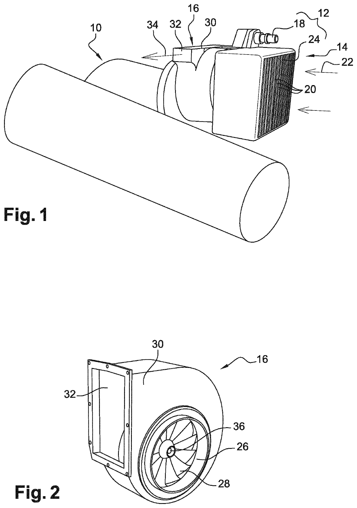
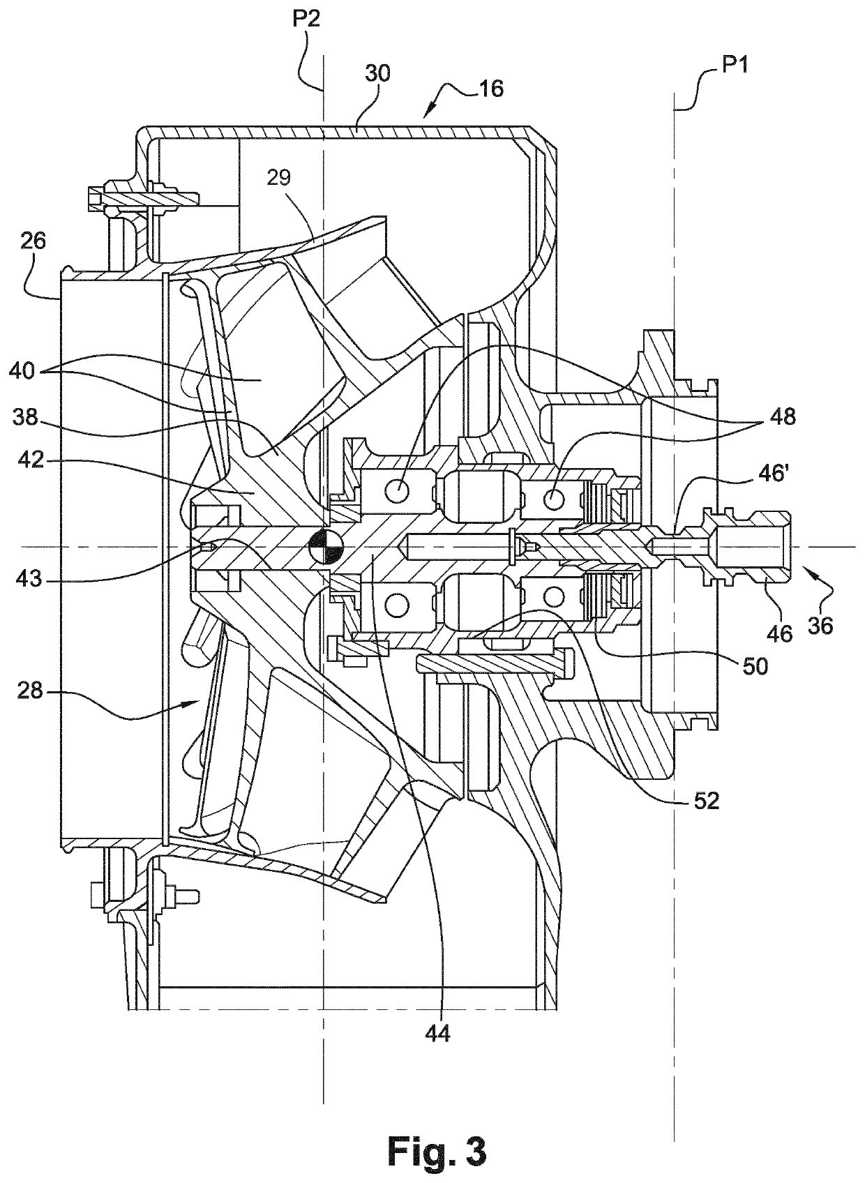
[0036]FIG. 1 shows an aircraft engine 10, here a helicopter engine, which is equipped with a cooling unit 12 for cooling the oil of the engine. The unit 12 comprises an air-oil heat exchanger 14 and a fan 16, which is best shown in FIG. 2.

[0037]The heat exchanger 14 is of the “brick” type and has a parallelepiped shape. It comprises an oil circuit connected to the oil supply and discharge ports 18, only one of which is visible in FIG. 1. It also comprises fins 20 defining heat exchange surfaces with an air flow passing through the exchanger (arrow 22). The front or inlet section 24 of the exchanger has a parallelogram shape. The outlet section (not visible) of the exchanger is also parallelogram shaped. A connecting pipe is assembled between the exchanger outlet section and the suction or inlet section 26 of the fan and provides fluid communication between these sections.

[0038]The fan 16 is here of the centrifugal type and comprises a wheel 28 which is driven by a shaft assembly 36 ...


PUM


Abstract

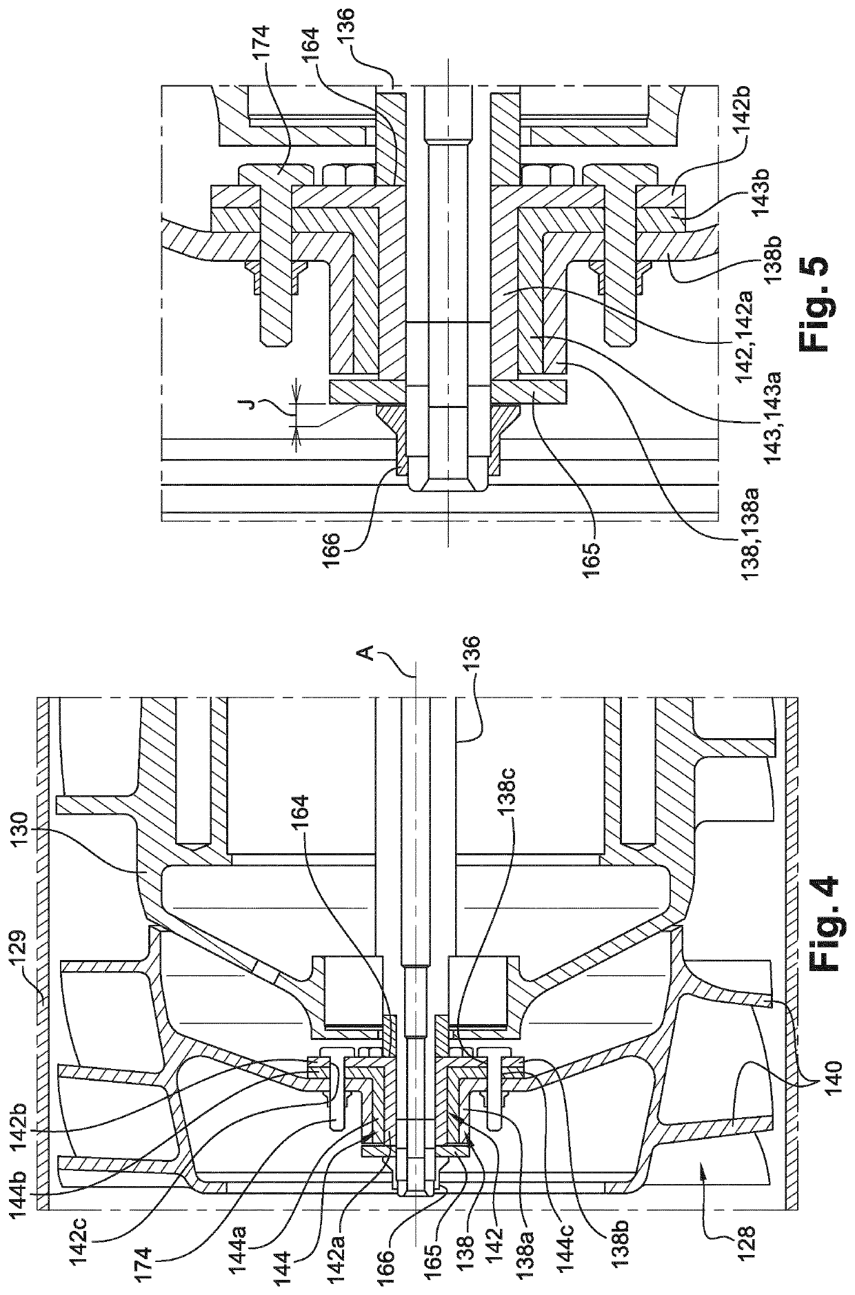
Fan (16), in particular for an aircraft cooling unit, having a wheel (128) comprising a hub (138) and an annular array of blades (140), a shaft assembly (136) for driving the wheel about an axis (A), and fusible means for connecting the hub of the wheel to the shaft assembly, said fusible connecting means comprising a first mounting sleeve through which the shaft assembly extends and which is surrounded by the hub, and fusible safety elements (174) which extend parallel to the axis (A) and are configured to break and to disengage the wheel from the shaft assembly when said wheel rotates and a driving torque of the wheel transmitted by the shaft assembly exceeds a certain threshold, characterised in that the connecting means comprise a second wearing sleeve (143) which is inserted between the first sleeve and the hub and through which the fusible elements extend, the second sleeve being made of a material which is different from that of the first sleeve and subject to wear by friction and / or by heating if the shaft assembly continues to rotate following the aforementioned disengagement.

Description

TECHNICAL FIELD[0001]The present invention relates in particular to a fan, especially for an aircraft cooling unit.BACKGROUND[0002]The background includes the document WO-A1-2017 / 046490.[0003]The aircraft engines are equipped with cooling units for fluids such as oil. An oil-cooling unit of the current art comprises an air-oil exchanger and a fan which is designed to suck air through the exchanger.[0004]The exchanger is generally of the “brick” type and the fan comprises a wheel which is arranged next to the exchanger and which sucks air through it so that the air takes the heat energy from the oil circulating in the exchanger.[0005]The fan is a mechanical fan and its wheel is driven in rotation by a shaft assembly that is connected to an output shaft of a gearbox or to mechanical sampling means on the engine of the aircraft.[0006]The engine manufacturers and / or helicopter manufacturers may require that, in the event of a problem with the wheel of the fan, such as a blockage of the ...

Claims


Application Information

Patent Timeline
Patent Type & Authority Patents(United States)
IPC IPC(8): F04D29/26F01D25/12F04D29/32
CPCF04D29/263F01D25/12F04D29/329F05D2220/323F05D2260/20F05D2260/311F05D2260/902F16D9/06
Inventor DEL RIO, FABIENSENTENAC, NICOLASSALVADOR, RENEGOESTCHEL, JEAN-YVES
Owner SAFRAN ELECTRICAL & POWER
Learn More