Clutch, in particular for a motor vehicle

a technology for clutches and motor vehicles, applied in the direction of fluid actuated clutches, clutches, non-mechanical actuated clutches, etc., can solve the problems of significant radial space requirements, detrimental to efficiency and measurement precision, etc., and achieve the effect of simple, effective and economical

Active Publication Date: 2017-08-15
VALEO EMBRAYAGES SAS
View PDF12 Cites 0 Cited by
  • Summary
  • Abstract
  • Description
  • Claims
  • Application Information

AI Technical Summary

Benefits of technology

[0020]The object of the invention is in particular to provide a simple, effective, and economical solution to the aforesaid problems.
[0022]The angular offset between the target and the detector allows the radial space requirement of the release bearing to be reduced. The target and the detector constitute a noncontact sensor.
[0025]It is thereby possible to limit the radial and axial space requirement of the release bearing while avoiding possible undesired interactions between the various targets and detectors, in order to ensure precise measurement.
[0028]Advantageously, the magnetic field of each target is directed toward the associated detector. In particular, in the case where several detectors are used, the magnetic field of each target is directed exclusively toward the associated detector and not toward the other detector or detectors, in order to avoid any undesired interaction between said targets and said detectors.

Problems solved by technology

In the case of the two aforementioned documents, the detector is arranged radially outside of the target and the body, resulting in a significant radial space requirement.
In addition, given the proximity of the two targets, undesired interference can exist between the targets and / or the associated detectors, which is detrimental to efficiency and to measurement precision.

Method used


Image

  • Clutch, in particular for a motor vehicle
  • Clutch, in particular for a motor vehicle
  • Clutch, in particular for a motor vehicle

Examples


first embodiment

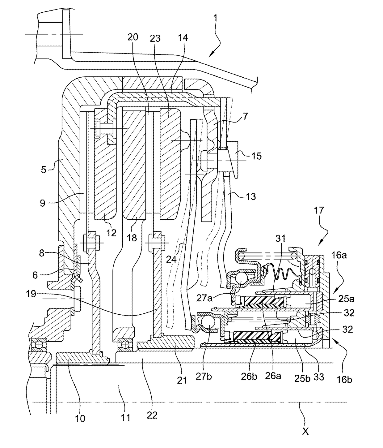
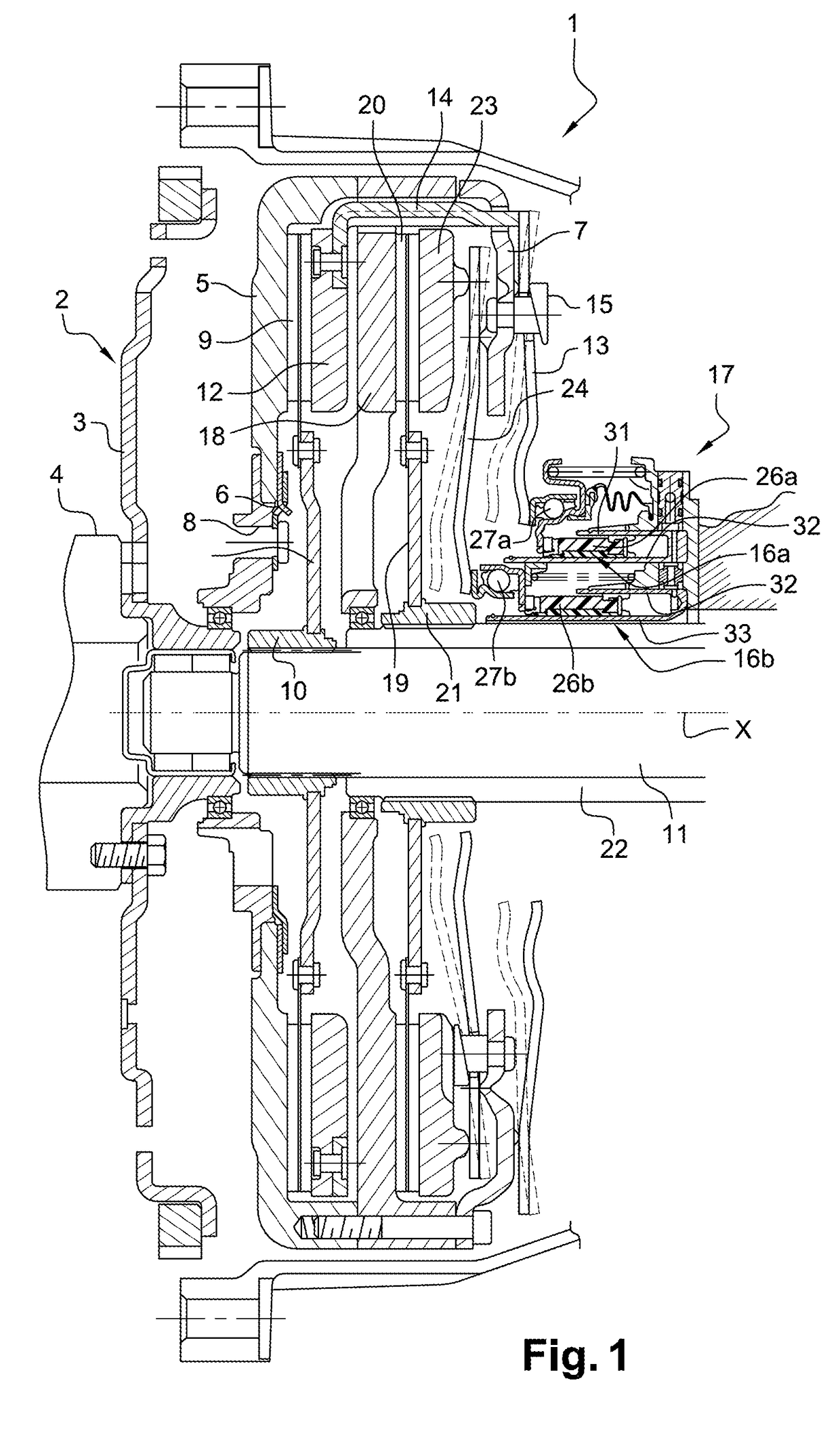
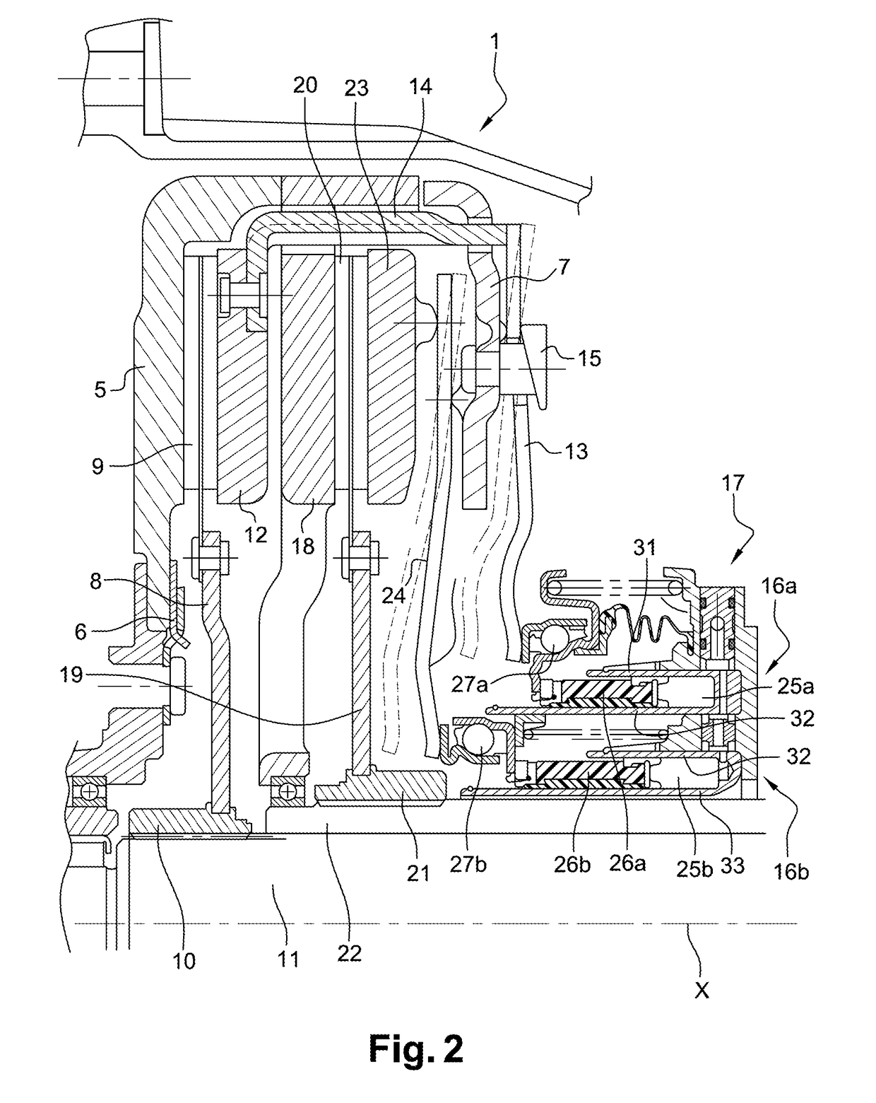
[0056]In a first embodiment illustrated in FIG. 3, release bearing 17 has a tubular body 30 comprising three concentric annular walls 31, 32, 33 delimiting between them two concentric annular spaces 25a, 25b into which pistons 26a, 26b of actuators 16a, 16b are engaged. These walls have also been labeled with the same references in FIGS. 1 and 2 that illustrate the existing art. The first, radially outer piston 26a is engaged into space 25a delimited between annular walls 31 and 32, and the second, radially inner piston 26b is engaged into space 25b delimited between annular walls 32 and 33.

[0057]In this embodiment, first target 28a is offset angularly, with respect to axis X, from first detector 29a and is located radially facing toward, or on the same circumference as, first detector 29a. First detector 29a and first target 28a are both located radially outside of annular wall 31. For this, first target 28a extends, for example, radially outward from first piston 26a.

[0058]Second...

second embodiment

[0060]FIG. 4 illustrates the invention in which first target 28a is located radially in the same plane R1 as first detector 29a. More particularly, first target 28a is located radially outside of first detector 29a, which in turn is located radially outside of wall 31. For this, first target 28a extends, for example, radially outward from first piston 26a.

[0061]In addition, second target 28b is offset angularly, with respect to axis X, from second detector 29b and is located radially facing toward, or on the same circumference as, second detector 29b. Second detector 29b and second target 28b are both located radially inside of annular wall 33. For this, second target 28b extends, for example, radially inward from second piston 26b. In this embodiment, first detector 29a and second detector 29b are located in a single radial plane R1.

third embodiment

[0062]FIG. 5 illustrates the invention in which first target 28a is located radially in the same plane R1 as first detector 29a. More particularly, first target 28a is located radially outside of first detector 29a, which in turn is located radially outside of wall 31. For this, first target 28a extends, for example, radially outward from first piston 26a.

[0063]In addition, second target 28b is offset angularly, with respect to axis X, from second detector 29b and is located radially facing toward, or on the same circumference as, second detector 29b. Second detector 29b and second target 28b are both located radially inside of annular wall 33. For this, second target 28b extends, for example, radially inward from second piston 26b. In this embodiment, second detector 29b is offset angularly from first detector 29a, second target 28b being located, for example, in the same radial plane R1 as first detector 29a and first target 28a.


PUM


Abstract

A clutch release bearing (17), in particular for a motor vehicle, having: a tubular body (30) through which at least one input shaft (11) of a gearbox is intended to pass; at least one actuator having a part, movable in translation along the axis (X) of the body (30), intended for actuation of a clutch diaphragm; a target (28a, 28b) whose position is representative of the position of the movable part of the actuator; and a detector (29a, 29b) capable of detecting the position of the target (28a, 28b). The target (28a, 28b) is offset angularly from the detector (29a, 29b) with respect to the axis (X) of the body (30).

Description

CROSS-REFERENCE TO RELATED APPLICATIONS AND CLAIM TO PRIORITY[0001]This application claims priority to Patent Application No. 1361172 filed Nov. 15, 2013 in France, the disclosure of which is incorporated herein by reference and to which priority is claimed.FIELD OF THE INVENTION[0002]The present invention relates to a clutch release bearing, in particular for a motor vehicle.BACKGROUND OF THE INVENTION[0003]A clutch conventionally comprises a reaction plate, a movable pressure plate, and a friction disk mounted between said reaction and pressure plates. Movement of the pressure plate is controlled by a diaphragm, which is turn controlled by a release bearing. The friction disk is rotationally linked to an input shaft of a gearbox, and the reaction plate is, for example, rotationally integral with a flywheel linked to the driving shaft, for example a crankshaft of an internal combustion engine.[0004]The release bearing is controlled by an actuator regulated by an electronic calculat...

Claims


Application Information

Patent Timeline
Patent Type & Authority Patents(United States)
IPC IPC(8): F16D23/14F16D25/08F16D21/06
CPCF16D23/143F16D21/06F16D25/08F16D25/083F16D2021/0669F16D2300/18F16D25/087F16D25/10
Inventor MOLLIER, CHRISTOPHE
Owner VALEO EMBRAYAGES SAS
Why Eureka
Try Eureka