Camera and image processor

a camera and image processor technology, applied in the direction of direction finders, instruments, television systems, etc., can solve the problems of inability to appropriately set the mask, inability to determine the edge portion, and inability to see the image of the suspicious person

Inactive Publication Date: 2009-05-21
HITACHI LTD
View PDF11 Cites 99 Cited by
  • Summary
  • Abstract
  • Description
  • Claims
  • Application Information

AI Technical Summary

Benefits of technology

[0011]In an image processor according to the present invention, it is possible to execute the mask processing on the basis of a three-dimensional mutual positional relationship between a mask area and a monitor object.

Problems solved by technology

However, there exists a disadvantage, that is, when an image of a suspicious person to be monitored enters a privacy mask area, the image of the suspicious person is invisible due to the mask.
However, even if the two-dimensional mutual positional relationship is employed, there exists a case in which the mask cannot be appropriately set.
However, for example, if the mask area overlaps an edge portion of the photographed image, it is not possible in the edge portion to determine whether or not the masking is to be performed for the moving object.

Method used


Image

  • Camera and image processor
  • Camera and image processor
  • Camera and image processor

Examples


first embodiment

[0022]The imaging device is an information terminal including, for example, a monitoring device such as a monitor camera, a camera such as a digital camera or a camcorder, or another cameral module. The image processor is an information processor to execute image processing, for example, a Personal Computer (PC) or a chip to process a video signal received from an external device. In the imaging device to be described below, it is possible by including information which represents the depth of a mask area and a motion area to determine the positional relationship relative to the imaging device between the target to be protected by the mask and the moving object. Also, the imaging device is configured such that on the basis of the positional relationship, an associated portion of the mask area is excluded.

[0023]In the description below, the space mask area is an area to be masked in an imaging space. The space mask area is indicated by use of the distance to a target of the mask prot...

second embodiment

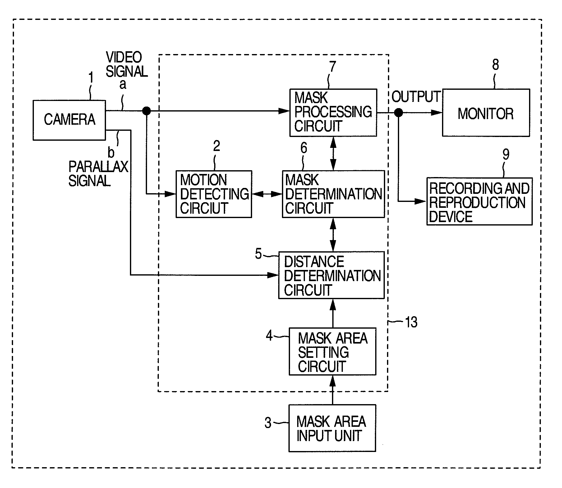
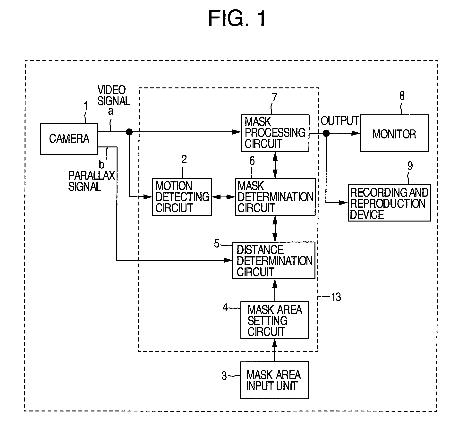
[0064]Description will now be given of a second embodiment, specifically, a monitor system including, in addition to the functions of the first embodiment shown in the block diagram of FIG. 1, image processing functions including a function to detect congestion and a function to detect a face as well as an alarm device.

[0065]FIG. 5 is a block diagram of an imaging device according to the second embodiment including, after the motion detecting unit 2 of the block diagram of FIG. 1, a congestion detecting unit 10 to cope with a state of congestion for a fixed period of time and a face detecting unit 11 to determine whether or not the motion detection target is a human to thereby appropriately determine the monitor target. In the description below, the duplicated part of description as that of the first embodiment will be avoided.

[0066]The congestion detecting unit 10 is a circuit to detect an abnormal state, namely, assumes an abnormal state if a person or an object keeps staying at a...

third embodiment

[0078]Description will now be given of a third embodiment of the monitor system in which based on the functions of the second embodiment shown in the block diagram of FIG. 5, the handling of the space mask area is changed. FIG. 7 shows an example of the mask processing in the embodiment when an area ranging from a floor of a bank to the outside thereof is photographed. In the embodiment, the space mask area 102 is arranged in a boundary zone of the internal area of the bank disposed before a window or an automatic door as an outer wall of the bank.

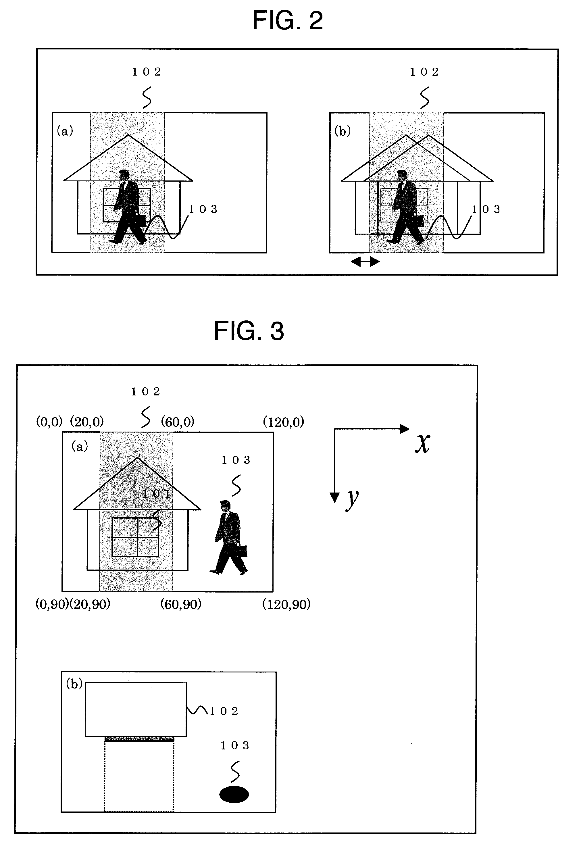
[0079]Section (1) of FIG. 7 shows an image in which an invisible space mask area 102 is set between the outside scene 105 to be protected and the person 103. Section (1′) of FIG. 7 is an image of (1) of FIG. 7 viewed from above in which the space mask area 102 exists between the person 103 and the scene 105.

[0080]Sections (m) and (m′) of FIG. 7, the person 103 approaches the external building 105 which is outside the bank and which is to b...


PUM


Abstract

A video signal produced through a shooting operation of a camera is sent to a motion detecting unit which detects a motion included in the video signal to set an area of the motion as a space motion area and inputs information of the area to a distance determination circuit which calculates distance between the motion area and the camera by use of a parallax signal produced from stereo cameras disposed in the camera to send information of the space motion area and the distance to a mask determination circuit. The mask determination circuit conducts a comparison between the space motion area information and the space mask area information and between the distance information of the motion area and that of the space mask area, and resultantly compares three-dimensional positions between the detected motion and the mask to determine a position relationship therebetween.

Description

INCORPORATION BY REFERENCE[0001]The present application claims priority from Japanese application JP2007-298783 filed on Nov. 19, 2007, the content of which is hereby incorporated by reference into this application.BACKGROUND OF THE INVENTION[0002]The present invention relates to an imaging apparatus and an image processor in which mask processing is executed.[0003]Recently, a video monitor or supervisory system employing a monitor or supervisory camera has been broadly used in locations and areas such as stores of a bank, an apartment building, a road, and a shopping district. To display and to record video information regarding such monitor areas in the system, it is essential to set a privacy mask for personal information included in the monitor areas.[0004]However, there exists a disadvantage, that is, when an image of a suspicious person to be monitored enters a privacy mask area, the image of the suspicious person is invisible due to the mask. The disadvantage is discussed in,...

Claims


Application Information

Patent Timeline
Patent Type & Authority Applications(United States)
IPC IPC(8): H04N5/225
CPCG08B13/19686G01S3/7864
Inventor GOTO, TAKEYUKIMARUYAMA, TAKASHIKIKUCHI, MAKOTO
Owner HITACHI LTD
Why Eureka
Try Eureka